
Author, Brett Weintz. Updated, 21 September 2020.
Hydrodynamic bearings typically have a limited number of failure modes, mainly involving a breakdown of the lubricant/ oil film (where oil film thickness is less than the roughness of the bearing/ shaft journal). However, the (root) causes can be numerous and having unique combinations/ sequences of contributory events. While onset of bearing damage may be detected by a high temperature or lubricant (debris) analysis, characterization and diagnosis of any damage generally requires the shafting to be dismantled for a visual examination of the bearing and shaft. Identifying the damage process, and hence cause(s), can be challenging as a result of progression in the damage mechanism and extent (with changes in appearance, texture, etc) at any time possibly obliterating the initial location characteristics.
On this page you can find a discussion of the principles and typical damage characteristics of hydrodynamic oil film lubricated plain bearings. Examples of damage are presented.
You can find the following Brabon Engineering Services site pages and case studies regarding ship propulsion shaft bearings:
- Ship sterntube aft bearing operations and problems discussion page.
- Hydrodynamic bearing design and damage discussion (this page).
- Ship vibration (shaft dynamics) discussion page.
- Shaft alignment measurements case study.
- Strain gauge shaft alignment measurement case study.
- Sterntube aft bearing machining offset accuracy case study.
- Fair curve alignment design example.
- Sterntube bearing problem case study 1.
- Sterntube bearing problem case study 2.
- Shaft alignment measurements Brabon Engineering Services undertake.
- Shaft alignment measurement details discussion page. Includes factors affecting derived results/ uncertainty.
- Shaft alignment principles discussion page.
Metallic (whitemetal) bearings – characteristics and failure modes
Metallic (white metal) bearings have well known features. Low coefficient of friction as well as good compatibility (low tendency for galling/ pick-up to occur) between bearing lining and shaft journal materials. This permits low speed operation/ inching with minimal damage. A thermal wipe associated with a transient event may involve only a small amount of lining being smeared a small distance with re-solidification being facilitated mainly by the high thermal conductivity coefficient(s) of metallic bearings, i.e. possibly allowing continued satisfactory operation. However, fatigue strength of the (soft) lining materials tends to decrease with increasing thickness of the layer, thus applications involving elevated loading (mean and vibratory) require multiple layers, such as in engine main bearings. Where the lubricant suffers (limited) contamination with particles, these can become impacted in the (soft) lining thereby reducing abrasive wear to the shaft journal and bearing allowing continued operation.
The predominant damage mechanisms for metal lined bearings include:
- Loss of hydrodynamic lubricant film due to lubricant starvation, leading to contact and thermal wipe/ smearing damage.
- Loss of hydrodynamic lubricant film due to overload, leading to thermal wipe damage.
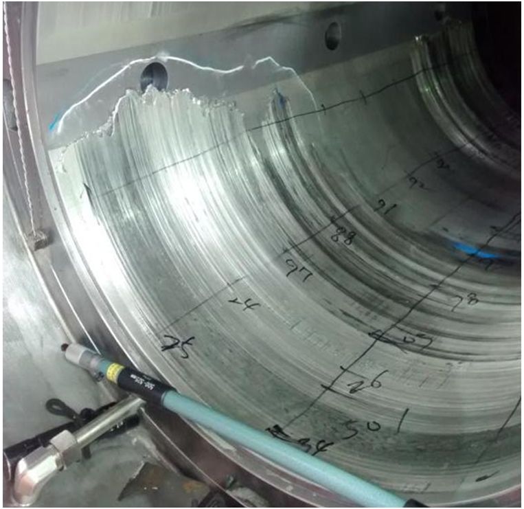
- Loss of hydrodynamic lubricant film due to edge/ biased loading, leading to localized damage, Figure 1.
- Fatigue damage to bearing surface (resulting in material loss and which may progress to thermal wipe damage), Figure 2. Identified by initial (mostly longitudinal) ‘wrinkle’ like marks on the surface. The ‘wrinkle’ marks become cracks that propagate down through the lining (perpendicular to the surface), eventually a number of cracks meet to form a boundary of a section of lining that detaches from the backing.
- Wear (material loss) of bearing surface and/ or shaft journal, e.g. as a result of particles contamination of the lubricant. Wear tends to be uneven (along the axis), and if the height between peaks and troughs is a similar magnitude to the lubricant film thickness, then progressive wear/ thermal damage may occur. Deviations in the axial load distribution may also compound this process. The journal surface finish (and bearing initially) has a significant effect on wear and surface roughness should be less/ better than 1.6×10^-6 m rms.
- Breakdown/ degradation of the lubricant and its properties, e.g. by oxidation or water contamination.
- A metallurgical imperfection in the bearing lining.
- Damage to the bearing surface due to corrosion or electrical discharge.

Stern tube aft bearing, thermal wipe damage, view on aft end port side, note thermal wipe at forward end (separate incident) Stern tube aft bearing, fatigue damage, view on extreme aft end stbd side 4 o’clock position

Less common and/ or application specific failure mechanisms of bearings include; overload/ contact by vibratory resonance involving the oil film (oil whirl associated with the fluid film stiffness) or the shaft beam (lateral vibration) as well as over-temperature of the bearing (possibly associated with elevated supply temperature and/ or insufficient flow), erosion wear, electrostatic discharge damage, breakdown of the lining, intermediate layers or backing (by delamination, collapse, etc), progression of underlying defect(s) and chemical reaction damage to the lining.
Further information on the appearance and classification of bearing damage can be found in the following:
- BS/ DIN ISO 7146:2008, plain bearings – appearance and characterization of damage to metallic hydrodynamic bearings.
- Many bearing manufacturers have also produced useful guides to identifying characteristic damage to bearings.
Non-metallic bearings – characteristics and failure modes
Non-metallic bearings also have well known accommodating features. In common with most bearings there is a low coefficient of friction and good compatibility between bearing lining and shaft journal materials. Bearing materials typically have low elastic modulus values (relative to say steel) allowing the bush surface to partially conform (deform elastically) under deviations of slope mis-match between the shaft journal and bearing possibly resulting in a reduced load bias between each end of the bearing (as compared to an equivalent metallic bearing). The bearings surface may also conform/ deform elastically in the loaded (circular) cross-section giving an improved geometry of the hydrodynamic oil film/ wedge, i.e. support over a longer arc with lower peak pressure. However, low thermal conductivity coefficients (relative to metal) result in heat removal being a key factor in design and operation. Non-metallic bearings may be tolerant to damage allowing continued operation after a damage incident (at reduced power levels) possibly until a convenient date for a repair activity.
Failure modes of non-metallic bearings are less well understood and vary with the particular material. However, observations indicate a related set of predominant damage mechanisms as follows:
- Thermal damage/ degradation of bearing material (which may progress to cracking, delamination, smearing, material loss, etc).
- Loss of hydrodynamic lubricant film due to lubricant starvation, resulting in running contact/ wear and possibly thermal damage.
- Loss of hydrodynamic lubricant film due to overload, resulting in running contact/ wear, etc.
- Loss of hydrodynamic lubricant film due to edge/ biased loading leading to localized damage.
- Wear (material loss) of bearing surface and/ or shaft journal. Wear may be irregular and, if the height between peaks and troughs (in the surface texture) is a similar magnitude to the lubricant film thickness, then progressive wear/ thermal damage may occur.
- If a bearing is comprised of multiple (axial) sections, then reduced lubricant film support at the abutments/ joints as well as variations in thermal growth (of the bearing wall thickness) may result in undulations along the length of the (lower) bearing surface.
Composite stern tube aft/ A-bracket bearing, abrasive wear damage Phenolic resin composite stern tube aft bearing lower half, port to left, note circumferential cracking at extreme aft end 4 o’clock position


Have you suffered inexplicable damage to a vessel’s shaftline or sterntube bearing?
Brabon Engineering Services can help by conducting accurate shaft alignment measurements and independent assessments.
Call for a discussion: +353 87 383 5043
email for a proposal: info@brabon.org
Send a message via our contact page
Connect on LinkedIn
Brabon Engineering Services would be pleased to review your condition monitoring data and provide a free honest and expert bearing damage risk assessment.
Oil film lubrication of hydrodynamic bearings
(How does a hydrodynamic fluid film slide bearing work?)
Hydrodynamic bearings function by the surface tension of the lubricant on the rotating journal producing shear (force) across the lubricant/ oil film thickness within the convergent geometry of the journal and bearing, with the shear in-turn generating pressure resulting in the shaft (load) being supported over an arc of (varying) distributed pressure, Figure 3.
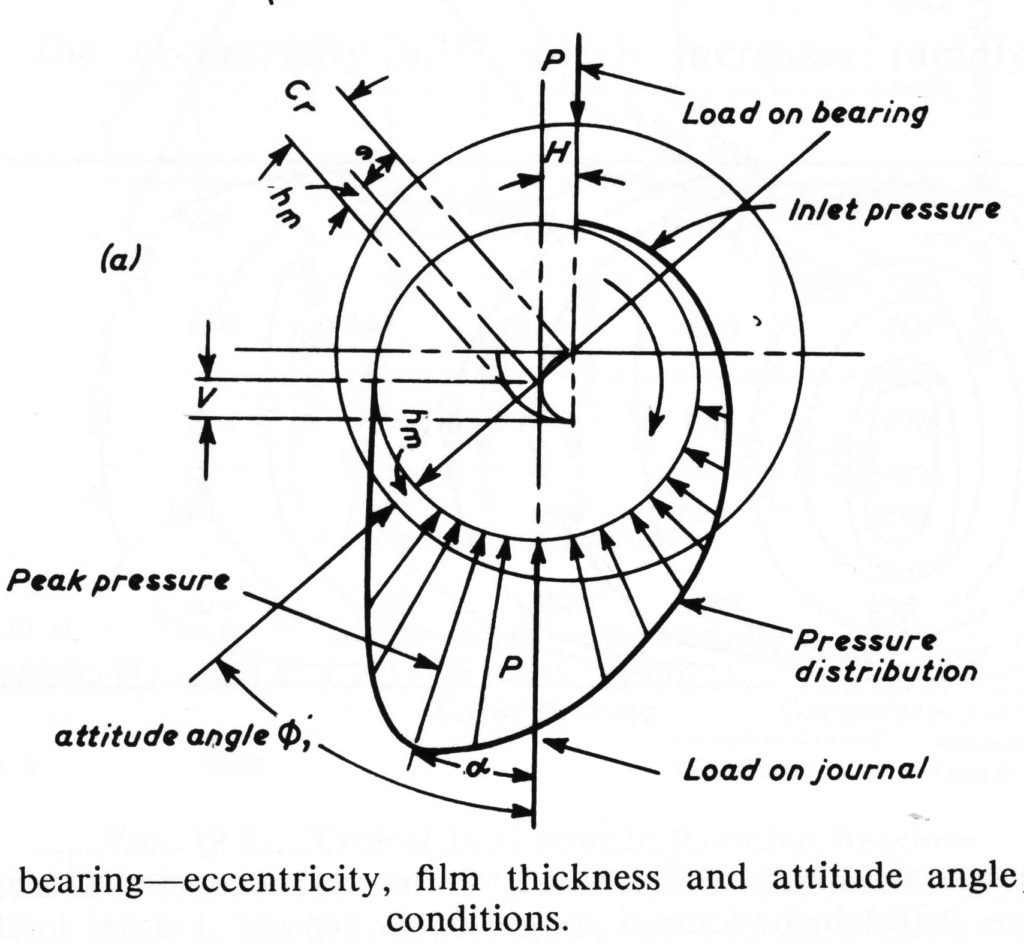
It can be seen that the oil film pressure, and the bearing surface pressure vary with radial direction as well as axial position depending on any shaft to bearing slope mis-match, temperature variations, etc. However, bearings are typically rated by nominal pressure, derived as follows:
nominal pressure, P = calc. bearing load/ (brg length x shaft diameter)
Sommerfeld number may be considered a measure of lubricant film stress in a (loaded) hydrodynamic bearing.
Sommerfeld No, So = (N.u/P).(r/c)^2
Where (So= Sommerfeld number)
N= Shaft speed, revs/sec
u= Lubricant absolute viscosity, N.sec/m^2
P= Nominal pressure, N/m^2
r= Bearing radius, m
c= Bearing radial clearance on shaft journal, m
With hydrodynamic oil film lubrication of bearings, the film thickness tends to increase with surface velocity (shaft speed) and lubricant viscosity, i.e. increasing Sommerfeld number. Lubricant viscosity typically decreases with increasing temperature (thus with heat generation may vary circumferentially and axially through the bearing). Considering a shaft resting at the 6 o’clock position on the bearing when stopped (with a load acting vertically down), increasing shaft speed causes the lubricant film to increase in thickness and the shaft centre to rise towards the bearing centre. For a plain circular sleeve bearing asymmetry and variation of the (tangential) friction forces result in the shaft centre following a theoretical semi-circular progression (curved against the direction of rotation) in shaft displacement between the 6 o’clock position and the bearing centre with increasing speed.
Considering a ship stern tube aft (plain sleeve) bearing, the propulsive (reaction) forces and moments on the propeller (are dominant) tend to result in an approximate straight line progression from the 6 o’clock position towards (about) the 2 o’clock position with increasing shaft speed, Figure 4.

Note that the shaft radial displacement progression within the bearing clearance changes significantly when the vessel is manoeuvred. During a port turn the shaft is lifted up to the 10 o’clock position (with a clockwise rotating shaft) in the bearing, while in a starboard turn the shaft is forced down to around the 5 o’clock position. The load on the stern tube aft bearing extreme aft end bottom position tends to be highest during starboard turns. In addition, should the shaft centre position move to where the bearing surface trailing edge meets the oil washway then the hydrodynamic oil film may be disrupted resulting in bearing damage.
The lubricant film pressure distribution, i.e. peak value and length of arc, is dependent on the oil film/ wedge geometry, i.e. bearing radius versus shaft radius (clearance), with a large clearance producing a high peak pressure with a small arc of support, whereas a small clearance results in a lower peak pressure and a longer arc of support. However, clearance affects the flow of lubricant through the bearing and given the lubricant contributes to heat removal from the bearing (and shaft), then insufficient clearance may result in elevated bearing temperature during operation. Conversely, an excessive clearance may result in a greater risk of local contact, i.e. a reduced load margin, as well as the increased flow of lubricant. A pressurised supply of fresh oil to the bearing provides significant improvement in load capacity/ performance versus simple flooded oil bath lubrication.
Tilting-pad bearings typically have a greater load capacity than plain cylindrical bearings. Tilting-pad bearings function by generating a (hydrodynamic) lubricant film pressure distribution on each pad. With a vertial downward load increasing speed the shaft centre follows a theoretical progression from the 6 o’clock position in a vertical straight line upwards towards the bearing centre.
Running friction is another factor in bearing performance. The nature of the friction/ lubrication acting between two sliding surfaces can be assessed by the Stribeck equation:
Stribeck number = (dynamic viscosity x speed) / load
Stribeck related the number to friction factor to indicated the lubrication mechanism (changes) for a given arrangement, i.e. progressing from boundary lubrication to fluid film with increasing Stribeck number.
Academic research has been conducted in novel materials with water lubrication, however despite the high heat capacity, water has a low viscosity adversely affecting the lubricant film thickness and also necessitates corrosion preventative measures. Laser surface textured bearings (with micro dimples) has also been the subject of academic research. However, reported results indicate improved performance is limited to low eccentricity conditions, i.e. low load suggesting little practical benefit.
Sterntube aft/ A-bracket bearing lubrication
Considering ship stern tube aft bearings, these long (2x diameter), plain cylindrical bearings are predominantly hydrodynamic oil film lubricated by means of a (flooded) oil bath together with natural/ thermal circulation and (small) forced supply arrangements. The oil bath arrangement is intrinsic to the load margin capability of the bearing. The fresh oil supply outlet may be be at the aft end between the bearing and the seal box (best case), or say 1m forward of the bearing (typical case) and may have a flow rate of only 0.5 cu.m/hour. Manufacturer’s have devised (heuristic) design guidance of bearing clearance versus shaft diameter and speed that have given satisfactory performance. Unfortunately, there has been little fundamental development to improve stern tube bearings with lubrication being predominantly by natural circulation and (relatively) large clearances to generate cooling flow, however, resulting in higher peak pressure/ lower minimum oil film thicknesses. A tilting-pad bearing design may bring greater load capacity margin, but would unlikely fit within the stern frame support structure envelope (typically the same size as the propeller hub diameter).
Improved lubrication arrangements for a plain cylindrical bearing design could develop a greater load capacity margin, and hence improved reliability. Future developments of novel combinations of (existing) available lubricant and bearing materials may also provide a greater load capacity margin for sterntube aft bearings.
For a stern tube aft bearing of whitemetal lined, oil bath lubricated, plain cylindrical design, the International Association of Classification Societies (IACS) requirements concerning machinery installations specify a maximum nominal pressure of 8 bar and a minimum length of 2.0 times the shaft (rule minimum) diameter. While the bearing length requirement distributes the load over a large area, it also creates a large lubricant film surface area for damping of any propeller shaft vibration.
For a stern tube aft bearing of synthetic rubber, reinforced resin or plastic material with oil (bath) lubrication and plain cylindrical design, IACS requirements concerning machinery installations specify a maximum nominal pressure of 6 bar and a minimum length of 1.5 times the shaft (rule minimum) diameter.
Further information regarding hydrodynamic bearings
The following case studies are available on request:
1. Stern seal and A-bracket bearing problems.
2. Stern tube aft bearing whitemetal fatigue damage.
3. Ship stern tube bearing damage risk assessment (discussion paper).
The Wikipedia article regarding plain bearings provides a description of construction, fluid film lubrication as well as details of lining material properties working temperature and nominal loading pressure limits. Wikipedia also have an article regarding (fluid film) hydrodynamic bearings, providing an outline of the principles, characteristics of operation and application examples.
~..~
