
A selection of brief discussions and practical tips regarding ship mechanical machinery failure/ damage problems based on experience acquired over the years as posted during 2020.
Any comments would be welcome.
28 November 2020, Ship propulsion shaft alignment
Replacement stern tube aft bearing design
Selection of design offsets for a replacement stern tube aft bearing in a shipyard repair case is aided by the following key measurement results (where the existing bearing sustained damage):
- Propulsion shaftline bearing loads as derived from strain gauge shaft bending and shaft jackings with the vessel afloat prior to dry-docking (with the damaged bearing). Including an estimate of the stern tube aft bearing load distribution.
- Optical/ laser alignment measurement of the existing (damaged) stern tube aft bearing surface offsets/ slope in way of the running/ worn area. (Relative to the stern tube reference line-of-sight.)
- Optical/ laser alignment measurement of the stern tube aft bearing housing slope (after extraction of the damaged bearing).
A robust calculation procedure to derive design of offsets for the replacement stern tube aft bearing is needed in order to optimise the load distribution on the bearing under operating conditions. There is usually an imperative for the alignment engineer to quickly deliver the new design offsets to allow the machining to commence. Making an educated guess for adjusted offsets based on the original design and the observed condition of the damaged bearing carries significant risk of precipitating a repeat failure incident.
(However, the difference between selected and original design offsets should be consistent with the correction indicated by the damage on the existing bearing.)
There may be multiple causes/ contributory factors to the original installation having suffered damage. For example, the bearing load capacity margin (at the aft end) may be overwhelmed during manoeuvring (especially during starboard turns). An adverse (forward-down) slope of the housing is a contributory factor in numerous stern tube bearing high temperature (thermal wipe) damage events. This can also occur on vessels where the stern tube construction involves a pre-manufactured flexi-tube.
See the shaft alignment principles and shaft alignment measurements pages for more information regarding ship machinery failure.
19 November 2020, Ship propeller shaft alignment
Stern tube aft bearing optimisation
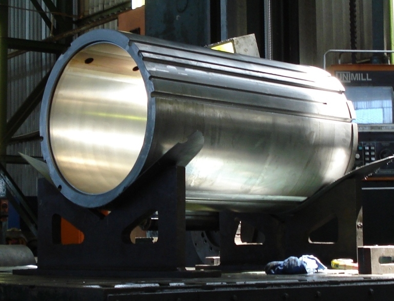
Oil lubricated ship sterntube aft bearings are 2x shaft diameter in length, e.g. for a 500mm diameter shaft the bearing is at least 1000mm long. This is to react the static load and propulsive hydrodynamic forces/ moments acting on the propeller. The large oil film area also aids in damping the vibratory element of propulsive forces from the blades acting in the unsteady wake in-flow.
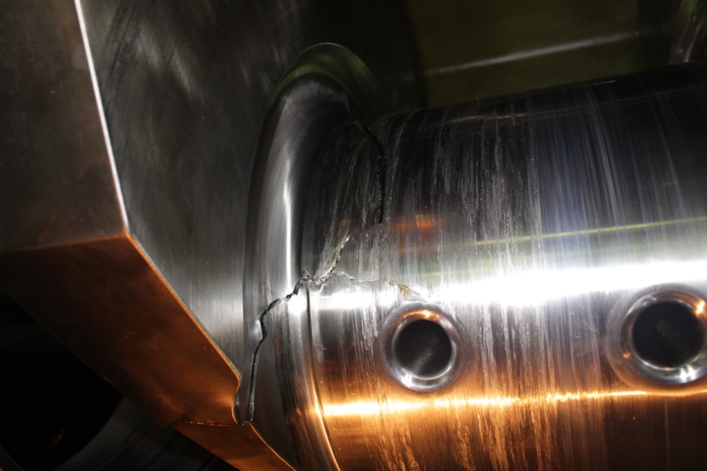
The difference in reaction loads at each end of the bearing is sensitive to slope mis-match between the shaft & bearing (as well as the forces on the propeller). Shaft bending due to forces on the propeller also affects the bearing load distribution. An excessive load bias on the bearing (edge loading) typically results in thermal wipe damage at the extreme aft end, 6 o’clock position. (A common failure mode problem.)
Brabon Engineering Services arrange/ adjust for a modest load bias to the aft end of the stern tube aft bearing in the stopped condition, i.e. so the forward end is not unloaded. This provides satisfactory operation at low shaft speeds as well as at the service speed.
29 October 2020, Ship propulsion shaft alignment measurements
Vessels not fitted with stern tube forward bearing
For vessels not fitted with a stern tube forward bearing basic bearing jacking measurements are not sufficient to verify the shaft alignment condition.
Ship designs without a stern tube forward bearing allow a more compact machinery block. This provides an optimised tonnage and lower port fees, etc. However, there are challenges in achieving a satisfactory shaft alignment condition, particularly for the sterntube aft bearing.
With such vessels strain gauge shaft bending measurements on the shaftline are one way to derive the load distribution between the aft and forward ends of the stern tube aft bearing. (Along with bearing jacking measurements in the propulsion engine to assess the overall shaft alignment.)
Shaft bending strain measurements are conducted with the vessel afloat at a representative draught (aft). For tankers and bulk carriers it may be suggested to measure in the laden and ballast conditions to verify satisfactory bearing loads under all operating conditions.
See the shaft alignment principles and shaft alignment measurements pages for more information regarding ship propulsion shaft alignment procedures.

7 October 2020, Diesel generator engine damage analysis
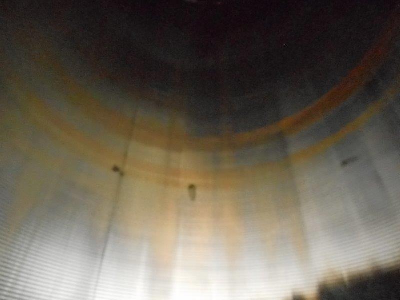
Ridge/ cam wear of crank pin journals
Marine and industrial diesel generators may suffer inexplicable ‘ridge’/ ‘cam’ wear of the crank pins under particular conditions. The damage is characterised by localised wear near the 6 o’clock position (relative to top dead centre) in two circumferential bands, one either side of the oil outlet. The centre area in-line with the oil outlet is a less worn area giving an apparent ridge or cam like form (relative to the worn areas).
The condition is identified by measurements of crank pin geometry. Test 1, using a straight edge to find the distinctive ridge near 6 o’clock. Test 2, measurement of crank pin diameter at various radial directions and axial locations. The bearing shells also tend to suffer wear in corresponding areas which can be quantified by thickness measurements.
The wear is usually a consequence of prolonged low load operation, e.g. <50% mcr, and is a particular risk if the lube oil system does not include a separator loop (or the separator is not run). Low load operation gives poor combustion with increased amounts of coke/ ash (an abrasive material) some of which may enter the lube oil.
At low loads the large end bearing loading is dominated by inertial forces from the piston/ connecting rod mass which are reacted at the crank pin 6 o’clock position (given low gas forces on the piston to counteract inertia). Note that generator engines are run at the service speed (for all loads). Many large end bearings have an oil pick-up groove giving less bearing surface around 6 o’clock (relative to the connecting rod axis). The combination of reduced oil film thickness (from elevated loading and lower bearing area) with abrasive particles in the lube oil can result in accelerated local wear of the crank pin in way of the bearing working areas.
See the diesel engine failure discussion page for related ship machinery failure information.

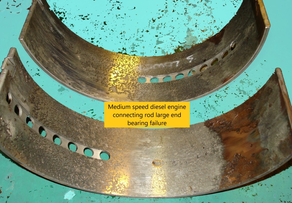
1 October 2020, Diesel engine failure analysis
connecting rod large end bearing cap
Many connecting rod large end failures are a result of the bearing cap bolts/ studs not being fully tightened.
Failures involving the large end bearing cap typically result in separation of the connecting rod leading to significant damage of the engine casing, connecting rod, piston and cylinder liner as well as the crankshaft. The bearing cap studs may fail by fatigue or tensile overload (depending on the initial tightening applied). Failure of the large end within a relatively small number of running hours following maintenance is also a strong circumstantial indicator of the (root) cause.
A report by the Swedish Club of hull and machinery claims over the period 2010 to 2016 found 192 cases concerning auxiliary engines among a total of 2,295 hull and machinery claims. Considering the 192 auxiliary engine failures, 58 cases involved connecting rod bolts (which was the greatest single factor).
Brabon Engineering Services would suggest that engine overhaul procedures include double-checking large end and main bearing cap to housing pairing (serial numbers) and bolt tensions. Engine manufacturer’s also recognise the inherent risks of disturbing the running gear assembly with many having deleted scheduled intermediate visual inspection (between overhauls) of large end and main bearings.
Note that fatigue failure of the bearing cap due to fretting wear between the large end bearing shell (back) and the housing may have a similar end result. But, examination of the components soon reveal a different scenario.
See the diesel engine failure discussion page for further ship machinery failure information.

23 September 2020, Strain gauge measurements
Bolt joint axial forces
Galileo said; measure what can be measured, and make measurable what is not.
Strain gauges are a means of finding actual strains in a component under trial/ service conditions, obviating assumptions of boundary conditions inherent in modelling analysis.
Cylindrical strain gauges for measuring axial tension in bolts/ studs are an interesting application. The gauge is epoxy bonded in a central hole within the axial area subject to tensile loading. The central location gives insensitivity to bending and the small diameter (~2mm) makes the gauge insensitive to torsional strain in the bolt, i.e. as torsional shear tends to zero at zero radius. The electrical bridge arrangement should also include an un-strained, temperature compensation gauge.
If possible, the bolt should be subject to a known tension to calibrate the output. Alternatively the, bolt material Young’s modulus and cross section area with the batch gauge factor can be used to derive sensitivity.
When a bolted joint is subject to an (external) axial load, part of the load is borne by an increase in the tension in the bolt (this is usually small), while the balance is reacted by a relaxation in the clamping force between the two flanges of the joint (generally the major proportion). If the joint is fitted with a gasket, the proportion of load variation between bolt shank and flange faces changes significantly. The distribution of load between the bolt/ stud tension and flange clamping force is determined by the stiffnesses of the two elements and derived using a bolt joint diagram.

17 September 2020, Ship propulsion shaft alignment
Main engine, main bearing load measurements
It is usual to periodically measure the main propulsion engine crank web deflections to monitor any progressive wear (effects) of the main bearings. It is also possible to find the bearing loads by means of jacking measurements to check the alignment condition.
The loads on the main engine three aft-most main bearings are a result of an interaction between the crankshaft and the coupled shaftline (as a continuous beam). Bearing loads also vary with engine thermal growth (temperature) and vessel draught aft (hull deflection due to additional water pressure).
Good measurements require patience and care when working inside the engine.
Measurement involves a hydraulic jack, strain gauge load cell (for accuracy) and a displacement sensor as well as a means to display/ record the data. The crankshaft is raised and lowered through the bearing clearance. A plot of the load vs lift data is examined to find the jack load at zero lift, hence the load that would be borne at the jack position (with no bearing).
As the jack is not located at the bearing axial centre, the jack load will vary from the actual bearing load. A Jack Correction Factor (JCF) is applied to derive bearing load. The JCF can be calculated by simulating the load transfer to the jack using a mathematical shaftline beam element model. Note, the JCF for main bearing 2 (numbering from aft) changes depending on the loaded state of main bearing 1 (flywheel). For example, the main bearing 2 JCF<1.0 if the flywheel bearing is lightly loaded (conversely MB 2 JCF>1.0 if the flywheel bearing has a significant load).
Measurements are conducted with the vessel afloat at an operational draught (aft) and the main engine warm (for results to reflect an operational condition). For tankers and bulk carriers it may be suggested to measure in the laden and ballast conditions to verify satisfactory bearing loads with the hull aft subject to deflection.
See the shaft alignment principles and shaft alignment measurements pages for more information.

9 September 2020, Propulsion reduction gearing alignment by shaft bending strain measurements
If you aren’t measuring the right things to begin with, you cannot achieve better results by more repeat measurements.
Satisfactory alignment of a reduction gearing unit to a (rigid) flange coupled shaft is assessed by the loads on the bearings either side of the main wheel. Gearing manufacturer’s typically recommend a maximum allowable load difference, in the vertical or horizontal directions, equal to about 25% of the main wheel (plus shaft) mass.
The main wheel aft/ output side bearing vertical direction load can often be measured by the bearing jacking technique (with the calculated jack correction factor). With some gearing designs it is also possible to undertake a jacking measurement at the main wheel forward/ non-drive side bearing. However, this feature is the exception rather than the rule. Thus, in many cases alignment is based on only the output side bearing load. Further, if the main wheel is supported by rolling element bearings, then jacking measurements are not possible (due to the lack of bearing clearance).
Alternatively, using the strain gauge technique it is possible to derive the loads, in the vertical and horizontal directions, on both bearings supporting the main wheel. Pairs of strain gauges are affixed at axial locations along the shaft coupled to the gearing output. Rotating the shaft through 180° provides the (total) bending strain in the shaft. The bending strains are then used to derive the bearing loads.
Measurements should be conducted with the vessel afloat at an operational draught (aft). Final confirmatory bearing load measurements should also be conducted on completion of trials with the gearing (foundation) warm.
See the shaft alignment principles and shaft alignment measurements pages for more information.

2 September 2020, Ship propulsion shaft alignment
Measurements for bearing damage analysis
There is an element of black art to ship shaft alignment.
Where bearing damage may be suspected we measure as-found shaftline bearing loads with the vessel afloat and propelling machinery stopped prior to dismantling. Bore alignment measurements of stern tube bearing and housing slope may then be conducted when the vessel is dry-docked & shafting dismantled.
To understand the cause(s) of the damage we consider the observed condition of bearings, the bearing loads as well as operational history and available condition monitoring data. At this stage calculated adjustments might be applied to any replacement bearing. Bearing load measurements are usually conducted after re-assembly in the afloat condition to confirm satisfactory load distribution between all shaftline bearings.
The selection of bearing offsets uses rules of thumb for satisfactory bearing performance in operation. When stationary, the shaft is subject to weight loads only and the journals contact the respective bearings. When running, the propeller is subject to hydrodynamic propulsive forces and moments (increasing with speed and typically exceed the weight at high power). Shaft journals are also supported along the full axial length by a lubricant film (generally). Fortunately, the lubricant film usually results in the shaftline (as a beam) being less sensitive to applied loads/ load changes. (Although bending in way of the stern tube aft bearing may increase.)
See the shaft alignment principles and shaft alignment measurements pages for more ship machinery failure information.

Have you suffered an unaccountable machinery damage problem?
Brabon Engineering Services will make a thorough investigation to help prevent further incidents and avoid compounding the total costs of the failure.
Call for a discussion: +353 87 383 5043
email for a proposal: info@brabon.org
Send a message via our contact page
Connect on LinkedIn
25 August 2020, Diesel engine failure analysis
Cylinder liner scuffing damage
Scuffing between piston rings and cylinder liner is an unpredictable damage mode.
Scuffing is a form of adhesive wear. Contact/ local welding between surface asperities of the rings and the liner can result in progressive damage to both components. Severe cases also involve smearing of the piston upper land(s) and skirt.
Piston rings work in an elasto-hydrodynamic lubrication regime, i.e. the lubricant film pressure interacts with deformation of the running surfaces. The surface speed cycles from zero to about 10m/s twice per stroke with temperatures greater than 500°C in the upper cylinder area. This is a demanding running environment.
There is a balance in roughness of the liner between a texture (with specific micro-profile) capable of holding adequate lubricant and a rough surface where metal-to-metal contact occurs across the lubricant film. Condition monitoring of acoustic emissions/ vibration can detect scuffing. But, the value here is the capability to limit the overall damage extent.
Lubrication conditions can be a factor, e.g. fuel dilution, lubricator injection rate, as well as the lubricant properties like ash formation and detergency. However as with many damage scenarios, there is rarely one single cause.
See the diesel engine failure discussion page for additional ship machinery failure information.
1 July 2020, Machinery failure/ damage analysis
Shaft seals
There is a school of thought that a shaft seal should leak a minute amount of fluid when running for lubrication and cooling of the contact lips/ faces.
Seal failure is a common problem with shafting systems, such as propeller shafts, pumps and turbo machinery. Lip seals may typically show a graceful degradation over time with wear of the lip and shaft/ liner surface. In general, a good surface finish on the liner and keeping the lip wet can provide a good service life.
Mechanical seals can typically provide a long operating life in high duty applications, i.e. pressure or speed. However, failure of mechanical seals can involve severe damage to the soft and/ or the hard face. Ensuring the static and rotating running faces are square to the shaft axis can sometimes be challenging, e.g. with small diameter shafts and seals fitted in a recessed housing.
Running the system without the seal cavity full of fluid will likely cause damage to any type of seal. Shaft dynamics can also result in seal damage, e.g. large radial displacement due to mechanical shock or adverse harmonic vibration. Shaft dynamics can occur as a result of bearing damage. This can present a chicken vs egg conundrum in attempting to understand the (root) cause of a failure where there is seal and bearing damage.
See the (ship) machinery failure/ damage investigation page for more discussion.

17 June 2020, Ship propeller shaft alignment
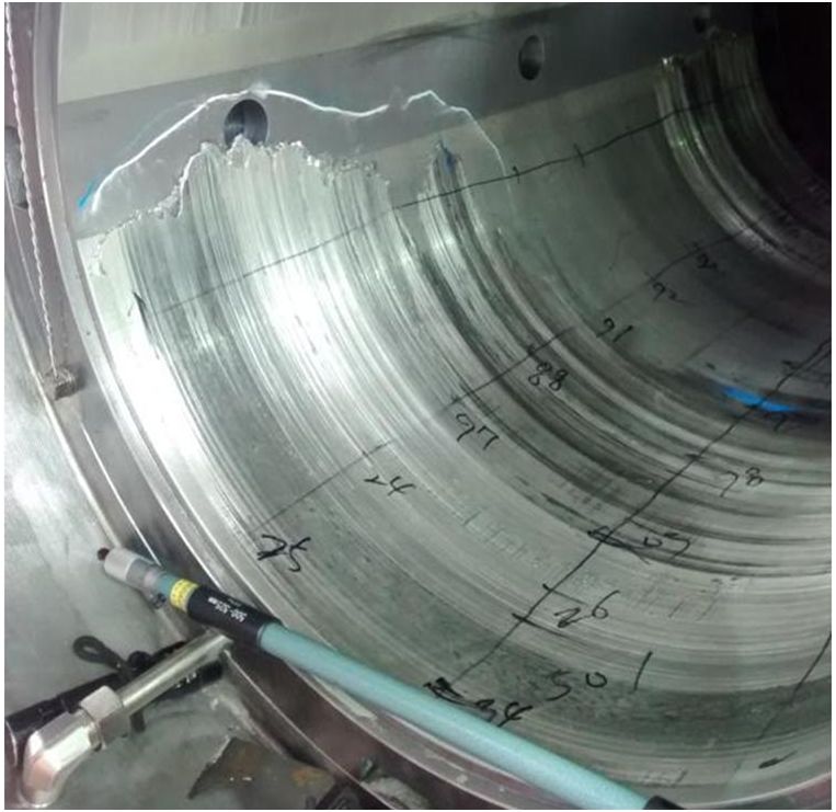
Sterntube bore alignment measurements
There is no measurement reference datum that is equal in straightness to a ray of light.
Bore alignment measurements are typically conducted in dry-dock after the propeller shaft is withdrawn to find the slope of the stern tube aft bearing as well as its housing. An alignment telescope or laser system is typically used for the measurement. A mathematical model of the shaftline (relating offsets to loads at each bearing) can then be used to calculate any offset adjustments for the stern tube aft bearing.
There are differing views as to the correct reference datums for a bore alignment measure. Brabon Engineering Services use the stern seal location recesses at the extreme aft and forward ends of the stern tube. This applies equally to the laser and telescope. The location recesses are accessible with the stern tube bearings in place or extracted. The stern tube also tends to be a heavily reinforced structure which will not bend greatly between the vessel being afloat or supported on dry-dock blocks. Thus, offsets measured within the stern tube (between the datums) will accurately reflect the afloat condition.
Some folks like to also measure offsets at intermediate/ plummer bearings and the prime mover output flange. However, it should be noted that a steel ship is a flexible structure. There will be considerable hull deflexions in way of the engine room (in the vertical longitudinal & vertical athwartships planes) between the hull being supported by water pressure versus support by blocks under the keel and bilge.
See the shaft alignment principles and shaft alignment measurements pages for more information.

5 June 2020, Ship propulsion shaftline bearing loads by strain gauges
The first rule of strain gauge measurements is that at least one gauge will have an awkward location.
Shaft bending strain measurements can be used to derive loads at additional shaftline bearings (beyond those accessible for jacking). This can include the load distribution between the aft and forward ends of the sterntube aft bearing.
Note that the loads derived by shaft jacking measurements do not correlate to one unique shaft alignment condition. This is important in the case of vessels where the stern tube is not fitted with a forward bearing. In such installations the load distribution on the stern tube aft bearing is mainly controlled by the chocks under the intermediate bearing. (Rather than the machined alignment between the sterntube aft and forward bearing housings.) Indeed, the intermediate bearing load derived by shaft jacking measurements does not provide assurance of a satisfactory alignment (load bias) of the propeller shaft in the stern tube aft bearing.
It can be shown that a family of alignment conditions for the stern tube bearing and propulsion engine produce the same intermediate bearing load. Strain gauge shaft bending measurements offer one of the few means of confirming satisfactory alignment on the stern tube bearing.
See the shaft alignment measurements page for further discussion.

28 May 2020, Machinery damage analysis
Whitemetal bearing operating temperatures
Most alarms do not affect the Operator’s heart rate. However, a bearing high temperature alert generally attracts attention and warrants immediate action.
Bearing alert/ alarm is typically set 10°C to 20°C above the anticipated maximum operating temperature. For ship shaftline bearings (not main gearing or engine main bearings) a typical alert temperature is 65°C. It should be stressed that the crucial factor is trend of temperature versus time or operating conditions, i.e. a significant temperature change near the alert level indicates action required.
Bearing manufacturer’s note an allowable maximum temperature on whitemetal of between 120°C and 150°C (Michell, Kingsbury, Renk). Whitemetal alloys start to melt at about 235°C (tin based) or 240°C (lead based). Note that the sensor arrangement affects the relationship of indicated versus actual lining surface temperature as well as the response time lag. For example, an RTD with spring contact to the backing metal in the peak temperature region will show a more accurate indication than a sensor loose in a tube near the bearing back, i.e. with air gaps. Oil outlet/ splash (close to the bearing) is also a means of monitoring bearing temperature. In addition, fatigue strength of the whitemetal lining is inversely related to its thickness.
Operating temperatures can vary depending on bearing arrangement. For example, an external lube oil supply will strongly control bearing temperature. Whereas an oil bath or self-contained lube system will reach a temperature depending on the thermal balance with the cooler/ conductive heat loss.
Considering lead versus tin based whitemetal alloys. Tin based whitemetal are superior to lead based linings for compressive yield and fatigue strength, see below. The downside of tin based alloy being difficulties in the casting process (particularly for large bearings).
Lead based, e.g. ASTM B23 grade 13 (6% Sn, 10% Sb, bal. Pb)
♦ Compressive strength for 0.2% strain of 35 N/sq.mm at 20°C.
♦ Compressive strength for 0.2% strain of 25 N/sq.mm at 100°C.
♦ Fatigue strength of 28 N/sq.mm at 10^7 cycles in rotating bending.
Tin based, e.g. ASTM B23 grade 11 (6.8% Sb, 5.8% Cu, 0.5% Pb, 87.5% Sn)
♦ Compressive strength for 0.2% strain of 63 N/sq.mm at 20°C.
♦ Compressive strength for 0.2% strain of 43 N/sq.mm at 100°C.
♦ Fatigue strength of 33 N/sq.mm at 10^7 cycles in rotating bending.
See the hydrodynamic bearing damage/ design as well as the ship sterntube bearing operation/ problems pages for more ship machinery failure discussion.

19 May 2020, Machinery failure and troubleshooting
Organizational improvement stimulation
It might be said that many engineers are focused on understanding the mechanics/ physics and causes of mechanical machinery damage and failures while ignoring the contributory organizational issues. We tend to obsess about lubrication, bearings, gearing, seals, etc. However, are many failure incidents only managed to the point of getting operational and back in service? Is there a ‘normal’/ ‘accepted’ mechanical equipment failure rate level for many vessels/ process plants?
Even when human error is a factor, actions to prevent future incidents are sometimes waived as ‘too controversial’. Perhaps continuous process improvement methodologies could be applied in many organizations particularly if applied in a non-antagonistic manner. Kaizen, six sigma and other techniques have been applied in many businesses to successfully reduce repair/ time off-hire costs as well as moderating the efforts directed to ‘fire-fighting’.
12 May 2020, Diesel engine failure analysis
Ship main engine damage trends
Report by marine insurance provider The Swedish Club of main engine damage trends within hull and machinery claims during 2015 to 2017 (link). They recorded 202 main engine failures (excluding turbocharger incidents) within a total of 1,219 hull and machinery claims (damage in excess of deductible limit) from a population of 8,758 ship-years.
The population of vessels included slow-speed, two-stroke and medium-speed, four-stroke engines in a proportion of about 70:30 (slow-speed: medium-speed). Although many vessel having medium-speed propulsion will have multi-engine installations, thus the ratio of engines would likely be less. Notwithstanding, the failure rate was the inverse at about 2.5:1 (more medium-speed than slow-speed damage incidents).
Causes of the main engine claims were categorised as follows:
- Lubrication failure, 40 cases.
- Incorrect maintenance or repairs, 19 cases.
- Poor fuel management, 11 cases.
The most frequently damaged parts were as follows:
- Cylinder liner, 32 cases.
- Crankshaft/ bearing, 28 cases.
- Fuel pump, 19 cases.
- Bearing, 17 cases.
Note that lubrication failures are likely to include a multitude of scenarios. Possible events include; lube oil degradation as well as bearing failure by oil starvation, fatigue, etc, cylinder liner wear/ scuffing and fuel pump plunger wear.
The report recommendations include testing bunker fuel, testing lube oil, checking purifiers/ filters and having a planned maintenance (scheduling) system as well as engine manufacturer attendance during major overhauls. The level of certainty in identifying the causes of each failure claim is unknown, and possibly only superficial. However, prima facie the recommendations suggest that many of the failures/ claims involved human error. Experience would also indicate that most failures are preventable.
Interestingly, the total claims included the following:
- 168 labelled as propulsion. This is a significant number of cases. Components affected may include; propeller, sterntube bearings, lineshaft bearings and shafting.
- 112 auxiliary engine cases.
- 76 turbocharger incidents (main and auxiliary engine), and
- 25 steering gear cases. These would include; rudder blade, rudder stock, bearings and hydraulics.
See the diesel engine failure discussion page for further related ship machinery failure information.

6 May 2020, Ship propulsion shaft alignment
Stern tube aft bearing operation and problems
An oil lubricated ship stern tube bearing is 2x shaft diameter in length, e.g. for a 500mm diameter shaft the bearing is at least 1000mm long. This is to support the static load as well as the propulsive hydrodynamic forces/ moments acting via the propeller. A long bearing also aids in damping the vibratory element of propulsive forces due to the propeller blades acting in the unsteady wake in-flow.
With a long bearing, the difference in reaction loads at each end of the bearing is sensitive to slope mis-match between the shaft journal and bearing. Shaft bending due to static and hydrodynamic forces/ moments on the propeller also affects the reaction loads at each end of the bearing. Metallic bearings are not tolerant of excessive load bias, i.e. edge loading. Thermal wipe damage at the extreme aft end, 6 o’clock position is a common failure mode. A sterntube bearing having a heavy load bias aft/ large slope mis-match would have a reduced tolerance (load margin) in the event of heavy manoeuvring at elevated shaft speed.
For optimum sterntube bearing alignment Brabon Engineering Services arrange for a modest load bias to the aft end of the bearing in the stopped/ static condition, i.e. the forward end should not be unloaded. This provides satisfactory operation at low shaft speeds. At high shaft speed/ power the thrust eccentricity is typically above the propeller centre and the net moment results in a load bias to the forward end of the bearing.

28 April 2020, Rotating machinery vibration analysis
Ship propulsion shaftline torsional vibrations
Torsional vibrations can sometime be a problem on ship propulsion shafting systems. Most two-stroke, diesel, direct drive propulsion systems pass through a torsional resonance during each run-up in engine revs to service speed.
Generally, elevated torsional vibrations provide no external signs of distress (up until when a failure occurs). Propulsion shafting torsional vibrations are mainly absorbed/ damped by the water surrounding the propeller. With no monitoring system, the ship Engineer can only make basic observations of the engine and any as fitted sensors.
On slow-speed propulsion systems, the following should be considered:
- Any deterioration in damper condition. Supply pressure to oil filled dampers should be in excess of the recommended minimum at all times.
- Intermediate and propeller shafts should be maintained free of potential fatigue crack initiation sites, e.g. corrosion pitting.
- Axial vibration should be monitored through the speed range. Note that axial and torsional vibration modes are coupled via the crankshaft.
On four-stroke main and auxiliary engines elastic coupling elements should be periodically checked for signs of heating or cracking. Control gear, e.g. clutch control or auto-synchronizer, should also be observed for correct operation.
See the ship vibrations page for further ship machinery failure information.

23 April 2020, Rotating machinery vibration analysis
Ship propulsion shaft lateral vibrations
Serious lateral vibration resonance of ship propulsion shaftlines is fortunately very rare. Over the years, I have only seen one suspected case.
The condition involves vibration of the flexible shaft in its beam modes (while rotating) in resonance with say, the propeller blade pass excitation (not imbalance). The linked videos (video1, video2) are a great demonstration of resonance of a classical Jeffcott rotor. A shaft with a cantilevered rotor, like a propeller shaft, would experience a similar mode shape. Note that the support stiffness significantly affects the critical frequency (particularly at the bearing adjacent to the rotor disc).
Lateral vibration is likely to only occur in shaftline arrangements having a long span between the sterntube aft/ A-bracket and sterntube forward bearings, with a slenderness L/D ratio greater than about 20. Damping of the propeller by the surrounding water as well as damping of the shaft in the bearings by the lubricant film will generally control/ limit propeller shaft motions.
Noticeable vibrations may occur in vessels having excessive bearing clearance, due to heavy wear, giving reduced oil film damping and support stiffness. (See Toms and Martyn, Trans. IMarE 1972.) An unloaded shaftline bearing would also effectively increase the shaft span (slenderness ratio) and possibly lead to lateral vibration. The sterntube forward bearing would be particularly sensitive to this condition. Significant excitation energy at the propeller would typically be required for resonance, such as heavy manoeuvring or running astern. Aside from vibration around the aft area, stern seal leakage would be another tell-tale indication of shaft vibration.
See the Brabon Engineering Services ship vibrations page for further ship machinery failure discussion.

21 April 2020, Ship propulsion shaft alignment
Bearing loads by shaft strain gauge measurements
Brabon Engineering Services affix strain gauges at selected axial locations along the accessible shaftline spans. Rotating the shaft through 180° provides the (total) bending strain in the shaft at each measurement location. The static shaftline vertical bearing loads are derived by a comparison of the measured bending moments with a mathematical model for a reference condition. Note that the derived bearing loads are dependent on the calculated weight of the (complete) propulsion shaftline assembly model.
Strain gauge shaft bending measurements can provide/ derive loads at additional shaftline bearings (beyond those accessible for jacking). This includes the load distribution between the aft and forward ends of the stern tube aft bearing. It should also be noted that the (jacked) loads at the accessible bearings do not correlate to one unique shaft alignment condition.
Brabon Engineering Services can undertake bearing load measurements with the vessel afloat or in dry-dock. Afloat condition measurements are more valuable and should be conducted at an operational draught (aft) and with the prime mover foundation warm. For tankers and bulk carriers it may be suggested to measure in the laden and ballast conditions to verify satisfactory bearing loads.
The technique can also be applied to derive bearing loads in any situation where a shaft assembly is supported by three or more bearings.
See the propeller shaft alignment bearing load measurements page for further discussion.

16 April 2020, Ship diesel engine failure analysis
Wear due to cat fines in fuel
Cat fines are hard, abrasive particles comprising compounds of aluminium and silicon. If an elevated concentration would appear in the main or auxiliary engine fuel supply, then damage is likely. Accelerated wear can occur to fuel pumps, injectors, cylinder liners and piston rings.
Marine hull and machinery insurance providers have reported incidents of severe engine damage due to cat fines. One scenario includes burning low-sulphur fuel oil (LSFO) that has not been purified. [Skuld note 3 July 2018, Cat fines causing claims. UK P&I Club technical advice circa 2017, Reducing the risk of serious engine damage caused by catalytic fines. Gard circular 01-14, Prevention of engine damage due to catalytic fines.]
Residual (RM) grade LSFO may contain up to 60 ppm of Al+Si (ISO 8217:2017 limit) and must not be mistaken for distillate (DM) grade fuel or gas oil. Engine manufacturers typically suggest an upper limit for Al+Si of 10 ppm to 15 ppm at the engine supply.
Bureau Veritas VeriFuel, marine fuel services report a global average Al+Si content of 19 ppm in VLSFO (2020 data) as well as 22 ppm in HSFO (2019 data). However in time, cat fines content may increase due to additional processing in refineries. Note that the above are averages, there will be variation between fuels from different refineries and crude stock. Hence, the need for diligence in sampling for analysis.
Prudent practice would be to periodically sample the fuel at the engine and at the settling tank as well as bunkers received. The analysis results for Al+Si can confirm satisfactory operation of fuel purifier equipment. In addition, the results can be correlated with cylinder drain oil analysis and engine inspections to optimise cylinder lube oil supply rate and base number as well as derive maximum life from cylinder liners and piston rings. Much comprehensive guidance is available from engine manufacturers, Classification societies and others. In addition, operators should be aware of the greater parafin like nature of LSFO. This brings risks of waxing at lower ambient temperatures.
With LSFO having a lower density and viscosity, centrifuges should theoretically remove a greater proportion of contaminants. Notwithstanding, fuel supplied to the separator should be at the correct temperature. Extra vigilance with cleaning the separator(s) is also needed during heavy weather. This is due to the tendency of accumulated sediment in bunker and settling tanks to become agitated and increase the Al+Si in the supply.
See the diesel engine failure discussion page for related ship machinery failure information.
Do you suspect a problem with a vessel’s propulsion shaftline bearing?
Brabon Engineering Services can help by conducting accurate shaft alignment measurements and independent assessments.
Call for a discussion: +353 87 383 5043
email for a proposal: info@brabon.org
Send a message via our contact page
Connect on LinkedIn
14 April 2020, Ship propulsion shaftline damage
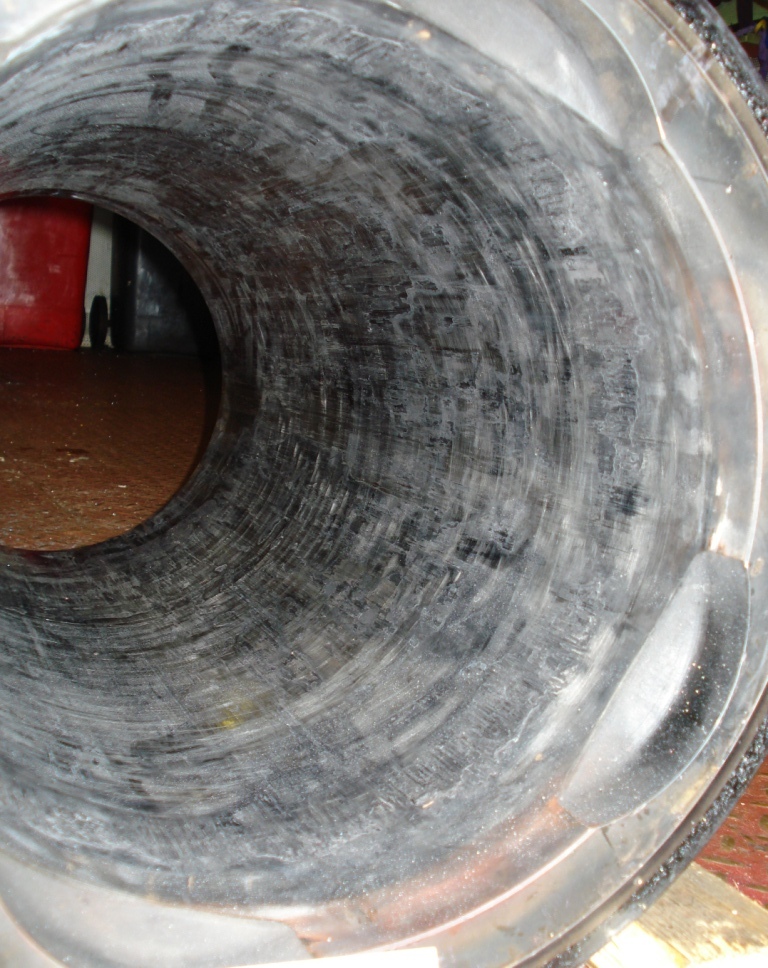
Water lubricated bearing damage trends
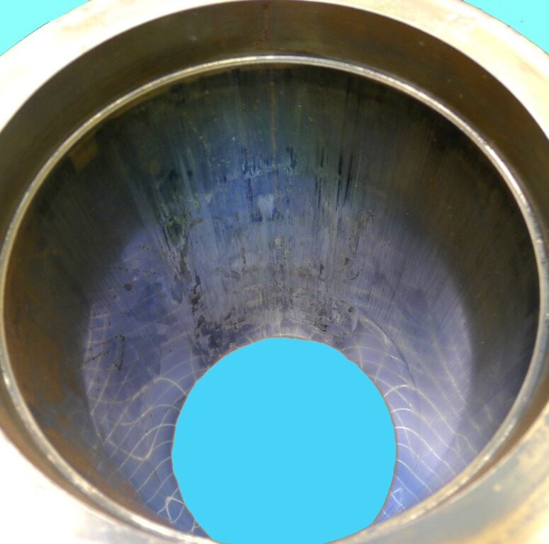
Heavy abrasive wear of water lubricated, non-metallic, sterntube and A-bracket/ P-bracket bearings can occur in numerous circumstances. Some examples:
- Prolonged running of open/ ambient water lubricated bearings in estuaries/ rivers having a large amount of suspended silt.
- Running closed-loop, fresh water lubricated sterntube bearing systems with contaminated lube water.
- Operation of open/ ambient water lubricated bearings after an extended idle period, i.e. weeks rather than days, having marine growth on outboard shaft journals.
Considering scenario three, rust never sleeps, and neither does marine growth. In this case, hard shell, marine growth, e.g. barnacles, can form on the shaft journal upper area (within the bearing clearance) during the idle period. Marine growth can occur on shaft liners of stainless steel SUS-316 and Monel metal (just like the propeller). When the vessel returns to service and the propulsion system is operated, then rotation of the shaft journal with its coating of hard shells can cause rapid wear of the bearing.
Scenario 3 may be relevant for cruise liners in temporary lay-up. For vessels that may possibly suffer damage, Brabon Engineering Services would suggest a prudent precaution of rotating propeller shafts say a few revs every day.
See the sterntube bearing discussion page for further ship machinery failure information.

9 April 2020, Strain gauge measurement system
Standing on the shoulders of giants. Electrical resistance strain gauges were invented in 1938 by Professor Arthur Rudge of MIT and separately by E.E. Simmons of Caltech in 1937.
Strain gauges are a means of finding actual strains in a component under trial and/ or service conditions. Measurements avoid assumptions of boundary conditions inherent in modelling analysis. Forces and support stiffness at boundaries can indeed be derived from measurement results.
Strain gauges can be affixed with the component in any orientation (working on vertical or inverted surfaces is slightly more difficult). The gauge factor (sensitivity) is used to directly find strain from change in resistance. If possible, the component should be subject to a known load to calibrate the output. Alternatively, the bridge circuit and indicated output can be checked by shunting the gauges with a precision resistor.
A Wheatstone bridge is used to measure gauge resistance variations. The circuit was invented in 1833 by Samuel Christie and “popularized” by (Sir) Charles Wheatstone in 1843. Where there are less than four active gauges, the bridge is completed with temperature compensation gauges or bridge completion resistors.
Measured strains can be converted to principal strains using Mohr’s circle of strain. Principal stresses can be derived from strain by the generalized Hooke’s law and the material modulus.
See the strain gauge measurements page for more discussion.

7 April 2020, Ship propulsion shaft alignment
Bearing loads by shaft jacking measurements
Ship propulsion shaftline bearing loads by jacking measurement. A tedious task that requires some patience.
The task involves a hydraulic jack and strain gauge load cell (for accuracy) located under the shaft adjacent to the bearing along with a displacement sensor as well as a means to display/ record the data. We raise and lower the shaft through the bearing clearance (being careful of any oil scraper). A plot of the load vs lift data is examined to find the jack load at zero lift (as with no bearing present), hence the load that would be borne at the jack position.
As the jack is not located at the bearing axial centre, the jack load will vary from the actual bearing load. A Jack Correction Factor (JCF) is applied to derive bearing load. The JCF can be calculated by simulating the load transfer to the jack using a mathematical shaftline beam element model. Note, the JCF changes if an adjacent bearing is unloaded. For example, the sterntube forward bearing JCF varies for single-point or two-point support in the sterntube aft bearing.
The vessel should be afloat at an operational draught aft and the prime mover warm during measurements. For tankers and bulk carriers we may suggest to measure in the laden and ballast conditions to verify satisfactory bearing loads.
See the Brabon Engineering Services shaft alignment measurements page for more discussion.

Bearing jacking arrangement Bearing jacking plot


26 March 2020, Rotating machinery failure analysis
Plain oil film bearing damage troubleshooting procedure
A suggested investigation process:
- Examine all components to identify the bearing damage mechanism, e.g. thermal wipe and/ or fatigue. The position of initial damage is important, e.g. to distinguish edge loading from oil starvation. However note, that damage can progress across a bearing surface.
- It is generally prudent to conduct bearing load measurements to eliminate possible overloading or unloading. Damage in the upper and lower halves may indicate dynamic shaft response possibly associated with an unloaded bearing.
- Collect operating trends of bearing temperature, lube oil supply and shaft vibration as well as alarm records from around the time of the failure. Temperatures of adjacent/ parallel bearings, e.g. port vs starboard or aft vs forward, can be compared to identify any early trends.
- Generate list of possible cause/ effect links and failure scenario sequences. Check-lists are useful as a prompt to consider the case from 360°. However, this does not negate the need for active thinking of scenarios. The timing of each step may be pivotal in the overall failure scenario.
- Critically review the scenario(s)/ intermediate conclusions and iterate the process. This loop is crucial to a successful investigation.
Seemingly intractable problems often involve multiple contributory factors. Identifying the cause(s) of problems and failures can inform changes to machinery operations/ maintenance so as to avoid further similar incidents and additional costs.
See the Brabon Engineering Services machinery failure/ damage investigation page for more ship machinery failure information.

23 March 2020, Ship propulsion
CIMAC strategy group zero carbon future
Papers concerning the pathway to a zero carbon future for the marine shipping industry. Includes discussion of future fuels (blue water operations) and hybrid options for short sea routes (link).
CIMAC March 2020 webinar on the global sulphur cap 2020. Presentation included discussion of potential problems (component wear, fuel compatibility) and guidelines for fuels in use (2020 compliant) fuels. Also an outline of fuels working group activities.

19 March 2020, Ship stern tube bearing damage troubleshooting
IACS recommended lube oil analysis alert limits
International Association of Classification Societies recommended stern tube lube oil analysis alert limits.
Water 1%, 10,000ppm
Sodium 80 ppm – sea water
Magnesium 30 ppm – sea water
Note, water contamination without high Na & Mg levels may be condensation in a header tank.
Lead 10 ppm – bearing lining, likely due to wear/ damage
Tin 10 ppm – bearing lining, likely due to wear/ damage
Copper 50 ppm – seal box or cooler, likely due to corrosion
Iron 30 ppm – shaft or sterntube, likely due to wear or corrosion
Chromium 10 ppm – stern seal shaft liners, likely due to wear
Nickel 10 ppm – shaft liners, likely due to wear
A increasing trend in bearing lining material warrants investigation. This should include a review of stern tube bearing temperature trends/ history for any high temperature event(s) or behaviour changes. For example, larger temperature changes on the stern tube aft bearing during turns (especially to starboard), or a larger temperature difference to the stern tube forward bearing. Bearing loads measurements may also be suggested. Bearing loads may confirm an adverse load distribution on the stern tube aft bearing. A heavy load bias to the aft end of the stern tube aft bearing is often linked with damage.
Sampling method is crucial to condition monitoring. Sufficient oil should be run off to clear the ‘dead leg’ for an accurate representative sample.
IACS do not advise a sampling interval. Some operators use a three month interval. But, for a vessel in service this may be about 2,000 operating hours. Such a period may not capture an event at an early stage in order to provide time for planning actions. We would suggest that more frequent sampling is better.
See the Brabon Engineering Services sterntube bearing failure/ damage page for more discussion.
16 March 2020, Ship machinery failure analysis
Marine hull & machinery claims statistics for 2018
Allianz Global Corporate and Specialty (AGCS) report that vessel total loss incidents has had a decreasing trend with 46 in 2018 versus the rolling 10 year average of 104/ year. The number of damage claims was steady at 2,698 in 2018. Machinery damage was the most frequent cause of casualty (~40% of all claims).
The Swedish Club also reported 1,197 machinery incidents from a total of 2,295 claims during 2010 to 2016, including 505 incidents with main & auxiliary engines.
Brabon Engineering Services would suggest the following categories of diesel engine failure causes:
- Overhaul maintenance, e.g. incorrect/ deficient replacement part, poor reassembly, parts kept in service beyond normal running hours limit. From experience, most failures involve this group.
- Routine maintenance, e.g. lube oil/ fuel condition (soot load, fuel dilution, cat fines), cooling system condition.
- Operation, e.g. prolonged low load.
- Manufacturing deficiencies in genuine parts.
- Electrical, e.g. critical sensors & connections.
Prudent preventative actions may include; staff training and a review of procedures. An important aspect would be to ensure robust double-checking of critical machinery before being boxed-up after maintenance.
See the diesel engine failure discussion page for related ship machinery failure information.

9 March 2020, Ship machinery damage troubleshooting
Engine room flood incidents
Engine room flooding incidents nearly always have serious consequences. The linked Chirp Maritime article describes a case of flooding via a fractured section of pipework within the engine room as a result of a dynamic pressure pulse (‘water hammer’) in the ballast system.
Other reported cases include:
- Flooding via burst section of valve body due to wastage/ corrosion of the cast iron.
- Water ingress via corroded steel stand pipes. That is the intercostal pipe between the vessel shell or sea chest and the valve.
- Engine room flooding during cleaning of the main sea water cooling system strainer. In this case, the main sea valve was not manually locked-shut and the control system malfunctioned causing the pneumatic actuator to open the valve.

5 March 2020, Machinery root cause analysis procedure
Identifying the cause(s) of problems and failures can inform changes to machinery operations/ maintenance so as to avoid further incidents/ costs. An outline root cause analysis process would be as follows:
- Collect operating trends and alarm records (timeline) from around the time of the failure.
- Closely examine all components to identify the fundamental damage process.
- Generate list of possible cause/ effect couples and failure scenario sequences.
- Critically review the scenario(s)/ intermediate conclusions and iterate the process. In considering hypotheses of cause/ effect/ sequence, greater weight should be given to commonly encountered scenarios (whereas unusual phenomena are less frequently encountered).
This loop is crucial to a successful investigation. The jigsaw pieces of the puzzle should fit together without the aid of a mallet, i.e. without more than one presumed element/ extrapolation.
Seemingly intractable problems often involve multiple contributory factors. The timing of each step/ link may also be important in the failure process.
See the Brabon Engineering Services machinery failure/ damage investigation page for more discussion.
27 February 2020, Diesel engine failure analysis
Main engine cylinder liner cold corrosion
Paper by CIMAC with detail discussion of two-stroke engine cylinder liner cold corrosion (link). Includes case studies of trade-off between cylinder oil feed rates using BN-70 versus BN-100. CIMAC also emphasise the importance of routine condition monitoring combining cylinder drain oil (lab) analysis, visual examination and liner bore measurements. In addition, all cylinders should be monitored, rather than a few selected units.
See the diesel engine failure discussion page for related ship machinery failure information.
25 February 2020, Ship engine room fire safety
Article by marine insurance provider GARD regarding ship engine room fires (link). Catastrophic events can involve multiple contributory factors, e.g. basic ship house-keeping and/ or accepting an oil mist detector alert as a ‘false alarm’. GARD emphasise the importance of maintaining a tidy engine room including the bilges, keeping sounding tubes, fuel oil service system and sampling points.
Historically, multiple significant incidents have been the stimulant for advances in safety systems. Perhaps the 21st century could be marked by advances in coordinated training of operational staff.
18 February 2020, Ship main engine problems during manoeuvring
Article by Chirp Maritime regarding incidents of main engine failure to start during manoeuvring.
Incidents of main engine failure to start included:
- When astern order given during approach to berth.
- During vessel departure from berth.
- During preparation to enter harbour after vessel had been drifting for some days awaiting a berth.
Associated causes involved start air (insufficient pressure), fuel supply interruptions and sensor failure (rare cases). Events occurred despite Pilot having requested tests of the main engine (as per normal practice). It would seem that crew preparation is key to avoiding this clearly dangerous situation.

15 February 2020, Ship machinery damage analysis
Auxiliary engine failure trends
Report by the Swedish Club of hull and machinery claims over the period 2010 to 2016. Breakdown of claims by affected ship system (damage in excess of deductible limit) was as follows:
- 2,295 total number of marine hull and machinery claims.
- 1,197 machinery claims.
- 313 claims concerning main engines.
- 192 cases concerning auxiliary engines.
The auxiliary engine cases involved the following factors:
- 58 cases involved connecting rod bolts.
- 27 cases of lube oil contamination.
- 25 cases of incorrect maintenance procedures.
- 16 cases involved an engine over-speed event.
- 4 cases involved latent component defects.
There are likely to be variations in the specific causes of each individual failure. Notwithstanding, the three situations above having the greatest numbers are likely to involve some form of human error, i.e. a significant proportion of cases. Thus, is there sufficient attention to implementing procedures to double-check the running gear after maintenance, e.g. are the large end bolts fully tight?
See the Brabon Engineering Services diesel engine failure discussion page for additional ship machinery failure information.

14 February 2020, Ship main engine problems and damage with low sulphur fuel oil
An article published by Safety at Sea Net highlighted main engine problems associated with change-over to low sulphur fuel. They note ports in California reported an increased number of main engine failure cases during 2015 following introduction of lower permissible sulphur emission limits.
Problems can arise due to thermal shock on engine fuel system, such as when introducing gas oil after burning HFO. In addition LSFO has reduced lubrication properties which can result in sticking and/ or wear of fuel pump plungers or fuel injector valves. Procedures for change-over should be checked against engine manufacturer’s technical guidance.

