
Author; Brett Weintz. Updated 17 November 2020.
Brabon Engineering Services can undertake strain gauge measurements on all types of components and outdoor structures. We can also supply and install reliable and accurate yet economical complete measurement systems. These can extend from the gauges through to an analogue or digital indication device with data logging. Systems can be stand-alone, or interface with your existing machinery monitoring system.
On this page you can find a brief introduction to strain gauge measurements. Including; applications, fundamentals, an outline description of affixing and testing as well as discussion of factors affecting accuracy of derived results.
Two case studies are presented, case study 1 and case study 2.
You can also find a description of strain gauge shaft bending measurements to derive bearing loads on the ship propulsion shaft alignment measurements page.
Engineering applications of strain gauges
Electrical resistance strain gauges (gages) provide a quick and convenient, i.e. not requiring major dismantling, means to measure deviations of actual strain in a structure/ component associated with changes in the loaded condition. Strain gauges find application in many industries. They are the main sensor type used for the measurement of force/ load, e.g. electronic kitchen scales and load cells in a weighbridge. They have been used to measure strain variations in crane and bridge truss elements under load. They have also been used in medical prostheses to confirm (dynamic) stresses/ forces.
Strain gauges are frequently used to investigate static/ dynamic torsional, bending or axial stresses in shafting. For dynamic measurements on a shaft, the gauges are typically connected to a battery powered digitizer/ radio telemetry unit temporarily fitted on the shaft. Shaft power and vibratory torque can be derived from torsional shear strain and rotational speed. This method avoids the need to dismantle or insert additional shaft elements.
Strain gauges are a proven method of investigating actual strains/ stresses in a component under trial/ service conditions, thus obviating assumptions of loading (and other boundary conditions) inherent in modelling analysis. Strain measurements can also be used to validate modelling results, i.e. modelling can be used to extrapolate field measurements. An example is shown in the case study below.
Strain gauges can be used for (dynamic) measurements on moving components to derive mean and vibratory stress as well as vibrational characteristics, i.e. frequency response and mode shape. Strain gauges can be used with components that work in adverse environments, e.g. under water or oil. In such cases protection is applied to the gauge(s), cables and cable gland/ transition as well as the associated signal conditioning electronics.
Strain gauge fundamentals
(How do strain gauge measurements work?)

Variations in resistance of the (active) gauges are measured by means of a Wheatstone bridge, see Figure. Where a measurement station has less than four active gauges, the full bridge is completed with temperature compensation dummy gauge(s) and/ or bridge completion resistors. The bridge is connected to a strain meter/ amplifier for indication/ logging the measured strain. The deviation in bridge output voltage is related to surface strain via the gauge resistance, bridge equation, number of active gauges (‘arms’) and the gauge factor for the particular batch of gauges.
The Wheatstone bridge output is the linear sum (within the typical range of use) of the variations in resistance and voltage on each arm (with the two diagonals having opposite signs/ senses).
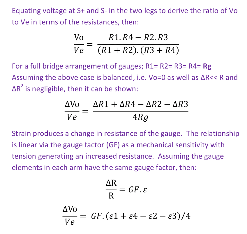
Thus, if a beam was fitted with gauges in a full bridge to measure bending, then R1 and R4 would be affixed on the top face while R2 and R3 would be on the bottom, i.e. subject to equal and opposite strain. A ‘hogged’ shape with tension in the top face would produce a positive sense of bridge output.

uniaxial strain gauge uniaxial gauge with two (independent) elements uniaxial gauge with (unstrained) temperature compensation dummy


Where uniaxial strain is measured and the gauges are aligned according to the physical load(s), i.e. the principal axes are obvious, stress can be derived directly using Hooke’s law (in two dimensions if strain in both principal axes are measured). It should be noted that the calculated stress is directly affected by any error/ actual variation in the material modulus. Derived (variations in) stress can then be related to bending moments/ forces using equations based on geometry and dimensions of the structure. In the general case, measured strains (using a three element rosette) can be converted to principal strains using Mohr’s circle (strain) and associated general equations. In turn, principal stresses can be derived from strain using the generalized Hooke’s law (for plane strain) with a value for the material modulus.
Strain gauge measurements – case study 1
A Client requested assistance with understanding the forces within the coupling bolts in a hose flange during winding on a reel. For a bolted joint subject to an external load, a portion of the load is taken by an increase in the bolt tension, while the balance of load borne by a reduction in pressure between the contact faces. That is, up to the limit of applied bolt pre-load. For a joint involving metal-to-metal contact the external load is mainly carried by the reduction in interface pressure and only a small increase in bolt tension occurs. This is due to the interface material volume having significantly greater stiffness than the bolt.
Bolt axial strain gauges
Test bolts were each fitted with cylindrical pattern, 1.5mm diameter, 3mm active length, uniaxial strain gauges. The gauges were fitted in a central 2mm diameter hole to measure strain at an axial position within the area of maximum tensile stress. An un-strained, temperature compensation gauge was affixed to the bolt head, and the two gauges were connected in a half Wheatstone bridge. An extension lead was fitted to connect the bridge to a strain digitizer and a computer for data logging.
The central location made the gauges inherently insensitive to bending in the bolt. The small diameter made the gauge insensitive to torque in the bolt, i.e. torsional shear tends to zero at zero radius. Each bolt was subject to tensile testing with applied loads up to 1 tonne to derive the relationship of indicated strain to actual load. (This would be more accurate than calculations using the batch gauge factor). This also provided a check of the output linearity, hysteresis and creep of the as-fitted gauges.
The coupling body was also fitted with gauges to measure axial (tensile) and bending strain. Testing was conducted with an axial load applied at the end, the hose pressurised and the coupling located at progressive angular positions around a semi-circular former. Loads in the test bolts as well as strains in the coupling body were recorded at different angular positions.
Bolted joint modelling calculations
The normally fitted coupling bolts had a different shank diameter to the test bolts. Bolt joint modelling was used to estimate the tension in the normal coupling bolts from the measured loads. Calculations confirmed that the normal coupling bolts would be subject to overload under particular conditions and that the hose bending stiffness was a contributory factor.
Do you have a measurement requirement or mechanical/ structural problem?
Brabon Engineering Services can help with accurate measurements as well as the associated calculations.
Call for a discussion: +353 87 383 5043
email for a proposal: info@brabon.org
Send a message via our contact page
Connect on LinkedIn
Strain gauge measurements – case study 2
Vessel
The case concerned a passenger vessel about 9,500 Gross tons with a twin screw diesel-electric propulsion system. The port steering gear had failed the Class rule maximum time limit of 28 seconds for the rudder to traverse from 35° to 30° of opposite helm.
The vessel had two balanced spade rudders each cantilevered from a rudder trunk tube that extended below the bottom of the hull and driven by a hydraulic rotary vane actuator. The rudder stock had a nominal diameter of 340mm and the complete assembly was supported by four bronze bearings. These were; a radial neck bearing at the lower end, a radial carrier bearing at the top of the rudder trunk as well as a radial bearing and thrust bearing in the hydraulic actuator. The stock was coupled to the rudder body and rudder actuator rotor with hydraulically tightened taper joints.
The hydraulic actuator had two pairs of internal chambers, with each pair of chambers being arranged on diametrically opposite sides of the rotor so as to develop (pure) torque in each direction. The actuator had a maximum operating pressure of 160 bar for a corresponding maximum torque of 170 kN-m. The port and starboard rudders each had a dedicated hydraulic power unit. Each hydraulic power unit comprised an oil tank, two electric motor driven variable output swash plate pumps as well as directional control valves, relief valves and a cooler.
Measurements and sea trials
Sea trials were conducted with dynamic measurements on the port and starboard steering gear during zig-zag manoeuvres at various speeds. Both rudder stocks were fitted with strain gauges for torque and bending in the span between the rotary actuator and the top of the rudder trunk (in addition to other sensors). The instrumentation was connected to a data logging system and computer to record the data.
Strain gauges
Rudder stock torque was measured using two chevron gauges bonded on diametrically opposite sides of the shaft and connected in a full bridge. The arrangement and wiring of two chevrons resulted in the bridge output being insensitive to shear force in the rudder stock, i.e. measuring only torsional shear strain. Rudder stock torque could be derived from torsional shear strain and the material (steel) modulus.
Rudder stock bending was measured in two planes 90° apart using two pairs of uniaxial strain gauges. The gauges in each pair were bonded at diametrically opposite positions. One gauge pair on was positioned to measure bending strain in the shaft in-line with the rudder blade. A second gauge pair was positioned to measure shaft bending strain at 90° to the rudder blade. Each gauge pair was connected in a half-bridge configuration. Each strain gauge bridge output was calibrated in-situ by shunting with a known (precision) resistance.
Bending in the rudder stock was derived from the axial strain and the material (steel) modulus. The transverse force at the rudder centre of pressure could also be estimated from a beam element mathematical model of the rudder stock assembly. This assumed a calculated transverse stiffness in way of the neck bearing at the bottom of the rudder trunk extension, i.e. an assumed deviation in alignment between the three radial bearings under load).
Conclusions
The sea trials measurements found port and starboard rudder stock maximum torque to be similar and within the rated capacity of the actuator and hydraulic power unit. Response of the port rudder (angle) was significantly slower than starboard during zig-zag manoeuvres. Port rudder stock torque, actuator pressure and hydraulic oil flow indicated an internal chamber-to-chamber leakage of hydraulic oil in the actuator.
Strain gauge and bridge installations
(How are strain gauges fitted?)
Installing strain gauges generally involves the steps shown below (many references are available):
- Preparation and cleaning of the area on the specimen for the gauge. Gauges can be affixed with the component in any given orientation. Although working on vertical and inverted surfaces is slightly more difficult.
- Alignment and affixing the gauge, typically using (plasticizer free) cyanoacrylate (‘super-glue’), polyester or epoxy adhesive. While cyanoacrylate affix nearly instantly, polyesters typically have a (relatively) long cure period and epoxy may require curing at elevated temperature. Notwithstanding, polyester and epoxy adhesives tend to be used for permanent instrumentation as they are more durable.
- Connection of the electrical cable(s) and arrangement of the electrical bridge circuit.
- Mechanical testing (of the surface bond) and electrical insulation testing.
- Application of protective coating/ material on the gauge and connections, etc.
In many instances the gauge and bridge configuration is chosen in order to measure strain due to one particular loading and to be insensitive to all other loadings. For example, two gauges affixed to opposite faces of the component and connected on the same side of a half bridge would measure bending while cancelling the effect of any net axial strain. The same gauges connected as diametrically opposite arms of a full bridge (with temperature compensation dummy gauges in the other two arms) would measure the net axial strain while cancelling any bending strain.
The strain meter indicated output is generally calibrated for the gauge installation. This is essential when the system includes a strain digitizer (radio) telemetry link between the gauges and the data logging/ indication unit. Calibration can be conducted by the application of a known load (which eliminates errors due to variation in material modulus). A known strain variation can also be simulated by shunting one arm with a (precision) resistor.
Indication/ recording instrumentation
(What is involved in a strain gauge measurement system?)
A strain meter/ digitizer is a purpose built instrument. The measurement process (of derived mV/V) needs to be ratiometric between the bridge output and excitation. That is, the derived mV/V is independent of excitation voltage, with good stability, i.e. minimal variation in derived mV/V versus time given no change in the gauge output.
Modern instrumentation arrangements typically involve analogue to digital conversion and data display/ logging with a computer. Brabon Engineering Services Limited use in-house prepared scripts in Python for data logging (accessing *.dll/ *.so and ‘C’ functions provided by instrument manufacturers). We also use Scilab (similar to Matlab) for data/ signal processing and calculations of principal stresses/ system forces/ moments.
Strain meter, Micro-Measurements D4, 4 chan (24 bit), USB communications to laptop Universal data acquisition device (strain, voltage, etc), Measurement Compution USB-2404-UI (24 bit), 4 chan, USB communications to laptop


Strain measurement errors/ uncertainty
While strain gauges give a continuous varying linear output, the indicated value is not infinitely accurate. Strain meters/ digitizers have typical resolution/ precision of about ±1 x 10^-6 mm/mm (±0.0005 mV/V bridge output). Thus using four active gauges (‘arms’) provides benefits in precision (and accuracy) when measuring small strains.
Given that a strain gauge is a resistor, the output is inherently sensitive to temperature. The gauge grid material is selected and treated in order to match the thermal expansion characteristics of the specimen material (self-temperature compensation). However, it is not possible to completely eliminate variations in output versus temperature with no change in loading. In general, strain gauge measurements in the field should use a Wheatstone bridge that is insensitive to temperature variations. This is achieved by having either, active gauges, or (un-strained) temperature compensation gauge(s) on both ‘arms’ adjacent to the bridge signal output.
Thermal effects can also cause drift in the bridge output (for no change in strain) under certain circumstances and require additional precautions. Circumstances can include; a specimen/ structure being subject to asymmetric thermally induced strains, e.g. differences in temperature between the ‘active’ and compensation gauges, or having anisotropic/ varying properties. Instrument drift, electrical tracking faults and external electrical influences can also be a factor. Accordingly, where best accuracy is desired for measurements of small strain variations, e.g. say less than 30 x 10^-6 mm/mm, conducted over longer periods of time, e.g. say hours, then additional measurements are generally needed. These might include; full bridge gauge configuration, measuring specimen temperature and recording no-load strain for the different operating conditions.
Cable effects as well as the bond between the gauge and specimen can also affect overall accuracy of the indicated results. The cables connecting the gauge(s) to the strain meter are part of the active circuit and affect bridge sensitivity. For a quarter bridge in particular, changes in lead wire resistance due to temperature can cause significant (spurious) variations in the indicated output. For this reason, field measurements using a quarter bridge gauge configuration are not recommended. The only exception being perhaps cases of short duration, e.g. seconds, or with high strain levels, say 500 x 10^-6 mm/mm.
It should also be noted that derived stresses are dependent on the Young’s modulus, or shear modulus, used in the calculation. Material modulus may deviate from values usually employed, e.g. 206.8 x 10^3 N/mm^2 for carbon steel. Academic research, such as [1], suggest variations may exceed 10% (with measured modulus being less than usual assumed values) and vary with strain rate, prior plastic strain as well as the chord on the stress/ strain curve used to determine the modulus.
Good practice is to measure/ record an entire load cycle, i.e. from no load to loaded and to unloaded. This will ensure the (initial) zero point was accurately set and capture any inelastic behaviour of the structure as well as any gauge/ adhesive creep.
[1 Zhong C, et al., Variation and consistency of Young’s modulus in steel, Journal of Materials Processing Technology, Vol 227, pp227 to pp243, 2016.]
Further information
A case study of ship propulsion shaftline strain gauge measurements is also available on request.
Suggested further reference information:
- Pople, BSSM strain measurement reference book, 1979.
- The Wikipedia article regarding strain gauges also includes descriptions of advanced strain measurement techniques.
- The British Society for Strain Measurement (BSSM) provide reference material, symposiums and training in strain measurements with electrical resistance gauges as well as other techniques.
~..~
