
Mechanical engineering consultancy
Thank you for joining with 1,000+ visitors per month to Brabon Engineering Services.
A small company giving 110% service
A consultancy providing specialist technical engineering assistance with understanding and resolving rotating machinery problems. Serving Operators/ Owners in the marine and energy sectors.
Services include; failure/ damage investigation surveys on all types of main and auxiliary mechanical machinery, ship propulsion shaft alignment measurements/ calculations, strain gauge measurements as well as engineering assessment/ design. Brabon Engineering Services is independent of any machinery manufacturer or shipyard.
Concerned about contracting with a small company?
With the depth of 30+ years of experience, academic knowledge as well as advanced tools, Brabon Engineering Services can assist you in understanding and resolving difficult situations. Having undertaken many challenging projects, I have the perseverance and grit to identify and assist in rectifying the root cause of your machinery problem.
As a small engineering consultancy Brabon Engineering Services are flexible to your requirements. There are also no unnecessary overheads in our fees which are focused on working time, not waiting or travel. Brabon Engineering Services can deliver better value for money than a larger company.
Technical engineering services
- Root cause analysis of mechanical damage/ failure to machinery using a highly disciplined logic process. Examples include; diesel engines, shaftline bearings, sterntube bearings, suspected excitation of shaft dynamics/ vibration or problems with lube oil/ cooling systems. An effective investigation is the means to prevent further incidents and avoid compounding total costs associated with the failure.
- Detailed ship shaft alignment modelling/ design calculations of bearing load distribution. Involves advanced modelling/ analysis tools and techniques.
- Ship shaft alignment measurements and assessments using advanced tools and techniques. Satisfactory alignment is the foundation for maximum bearing life (reliability). Tasks include:
- Sterntube bore alignment offsets using the Taylor-Hobson micro-alignment telescope and targets. Experience has shown the Taylor-Hobson optical kit is superior as a complete system to laser alignment. Post-processing image analysis/ scaling assures an accuracy of better than 0.01mm.
- Shaftline bearing loads by shaft jacking using strain gauge load cell and displacement transducer with computer data logging. Automated analysis of jacking data (results available immediately).
- Main engine, main bearing loads by crankshaft jacking. Engine crank web deflection measurements.
- Bearing loads by shaft bending strains (strain gauges). Advanced analysis techniques are applied to derive bearing loads beyond the accessible spans.
- Measurement of alignment/ offsets of elastic couplings and cardan shafts. Gap and sag of uncoupled intermediate shaft sections (preliminary alignment).
- Assessment/ interpretation of measured bearing loads (versus design).
- Calculations of bearing offset adjustments and predicted load changes for optimised local alignment and shaftline bearing load distribution.
- Review of (sterntube) bearing operating and condition monitoring data to provide a risk assessment of bearing damage.
- Strain gauge field measurements as well as any calculations of stress/ applied force. Components/ structure may be situated outdoors. Best practice is applied in gauge configurations/ installations along with best quality digitizers/ measurement devices. We can also supply complete measurement systems from gauges through to indication device or monitoring system interface.
- Engineering calculations, mathematical modelling and design. Examples include; classical mechanics, pipework systems, finite element modelling, data analysis (using Scilab/ Python) as well as CAD drawings.
- Preparation of formal written reports of the highest standard.
Have you suffered an inexplicable machinery problem?
Brabon Engineering Services will conduct a meticulous investigation and help prevent further incidents.
Call for a discussion: +353 87 383 5043
email for a proposal: info@brabon.org
Send a message via our contact page
Connect on LinkedIn
“He who learns but does not think, is lost! He who thinks but does not learn is in great danger.” Confucius
Ship machinery discussion topics
(Practical tips from experience over the years.)
30 July 2021, Ship machinery failure analysis
Diesel engine failure trends
Engine connecting rod large end failures are often the result of bearing cap bolts/ studs not being fully tightened.
These failures typically result in separation of the large end leading to significant damage of the engine casing, connecting rod, piston and cylinder liner as well as the crankshaft. The bearing cap studs may fail by fatigue or tensile overload (depending on the level of under-tightening applied). Failure of the large end within a relatively small number of running hours following maintenance is a strong circumstantial indicator of the (root) cause.
Engine overhaul procedures include double checking large end and main bearing cap to housing pairing and bolt tensions. Engine manufacturer’s recognise the inherent risks of disturbing the running gear assembly with many deleting scheduled intermediate visual inspection (between overhauls) of large end/ main bearings.
Note that fatigue failure of the bearing cap due to fretting wear between the large end bearing shell (back) and the housing is a different scenario, but, may have similar catastrophic results.
See the diesel engine failure page for more information.

1 July 2021, Ship propulsion shaft alignment
Sterntube bearing high temperature
A sterntube bearing high temperature event can cause severe anxiety for the vessel technical management team. The sterntube bearing is a vital element of the propulsion system and subject to significant range of loads and loading vector/ directions. However, the remote location places a reliance on condition monitoring data in the event of suspected damage.
High temperature events, and associated damage, can involve multiple contributory factors, but adverse operating conditions are often the trigger, for example:
- Heavy manoeuvring at service speed, e.g. emergency stop or zig-zag.
- Course control in heavy weather, e.g. in a quartering sea.
- Operation in the ballast condition with slightly high shaft speed or heavy manoeuvring.
- Sea water contamination due to seal failure.
A bearing temperature that exhibits repeated spikes, or a sustained high temperature, suggests a problem that would ultimately require repair. If the bearing temperature behaviour returns to normal, then examination of subsequent temperature and oil analysis results would be prudent to understand the risk of future incidents. If damage occurs at a location remote to the temperature sensor, then any temperature variation may be small and oil analysis may provide the only trend of any progression.
Detailed analysis of the condition data may reveal more than might be initially anticipated. Conversely, poor temperature/ operation records or infrequent/ poor lube oil sampling may raise more questions than answers.
Confirmatory shaft alignment bearing load measurements may be a prudent action. However, wear may result in only subtle variations with perhaps a reduction in sterntube aft bearing, aft end load bias. In addition, previous measurements at a similar draughts condition are rarely available for comparison.
See the page regarding sterntube bearings for more information.
24 June 2021, Ship propulsion shaft alignment
Suspected sterntube bearing damage
If sterntube bearing damage is suspected, then a coherent process should be applied to confirm and identify if a problem exists. The following information can prove useful to converge on a judgement:
- Bearing temperature may be the first indication of a problem. If damage occurs at a location remote to the temperature sensor, then any temperature variation may be small. Analysis of temperature history may trend any progression, e.g. aft versus forward bearing, aft bearing versus ambient sea water.
- Oil analysis trends of bearing debris concentration can provide indication of progression. Any partial oil changes need to be accounted. For oil lubricate non-metallic bearings, oil analysis is typically limited to water content. In this case, sterntube lube oil circulation strainers can be inspected for debris and any smell of burnt phenolic.
- If an air seal is fitted examination of debris from the drain tank may provide evidence of damage at the extreme aft end.
- Poker gauge measurement of weardown is a prudent action. However, this is generally only useful for non-metallic, water lubricated bearings. Damage to oil lubricated bearings typically results in weardown within the measurement uncertainty range (except in extreme cases).
- Confirmatory shaft alignment bearing load measurements. However, wear may result in only subtle variations with perhaps a reduction in sterntube aft bearing, aft end load bias. Previous measurements at a similar draughts condition are generally not available for comparison.
See the page regarding sterntube bearings for more information.

17 June 2021, Unusual mechanical failures
Torsional vibration of ship propulsion shaft
Failures due to torsional vibration are unusual given most systems are subject to design stage analysis. Torsional vibrations are mainly absorbed/ damped by the water surrounding the propeller. Elevated torsional vibrations may provide no external signs of distress. Although vibratory reaction forces may occur with diesel direct drive or geared reduction systems.
Two-stroke, diesel, direct drive systems pass through a torsional resonance in every run-up to service speed revs. The barred speed range should not be transited slowly. Care should be taken with condition of the TV damper, e.g. oil supply pressure. Intermediate and propeller shafts should also be free of potential fatigue initiation sites, e.g. corrosion pitting.
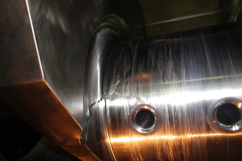
Design analysis must consider modes involving all combinations of branches and excitations. The failed elastic coupling shown was from a propulsion system having two medium speed diesels to a combining reduction gearing set driving the propulsion shaftline. With both engines clutched-in and running at idle, a 0.5x order excitation, due to imbalance between cylinders, excited a torsional resonance involving both engines in anti-phase, i.e. 1-node mode not involving the propeller shaft branch.
Learn more on the ship vibration page.

9 June 2021, Ship propulsion shaft alignment
Vessels with no sterntube forward bearing
Vessels designs without a sterntube forward bearing allow a more compact machinery block. This provides an optimised tonnage and lower port fees, etc.
The sterntube aft bearing load distribution is then mainly controlled by the intermediate bearing. However, the intermediate bearing offset is not inherently set as is the case where a sterntube forward bearing is fitted.
Shaft jacking measurements at the intermediate bearing are not sufficient to verify the shaft alignment condition. Strain gauge bending measurements on the shaftline are needed to derive the load distribution between the aft and forward ends of the sterntube aft bearing. Bearing jacking measurements of the main engine, main bearings then verify the engine alignment. The afloat bearing load measurements inform adjustments of any replacement sterntube aft bearing.
Measurements should be conducted with the vessel afloat at a representative draught (aft). In dry dock the vessel is supported by keel blocks which cause significant hull deflection, thus bearing loads in this condition should not be used for adjustment calculations. For tankers and bulk carriers it may be suggested to measure in the laden and ballast conditions to verify satisfactory bearing loads under all operating conditions.

2 June 2021, Ship propulsion shaft alignment
Bearing loads by shaft jacking measurement
A task requiring patience, or you might say bearing jacking measurements are quite tedious.
Involves a hydraulic jack, strain gauge load cell (for accuracy) and a displacement sensor as well as a means of real-time display and recording the data. The shaft is raised and lowered through the bearing clearance (being careful of any oil scraper). A plot of the load versus lift data is examined to find the jack load at zero lift with no bearing, hence the load that would be borne at the jack position.
The jack is not sited at the bearing axial centre, jack load will not equal actual bearing load. A Jack Correction Factor (JCF) is applied to derive bearing load. JCF can be calculated by simulating load transfer to the jack with a mathematical shaftline beam element model. Note that JCF varies if a shaftline bearing is unloaded. For example, if the main engine aftmost main bearing is loaded then the JCF for main bearing 2 will be greater than 1.0 (e.g. 1.2), if the aftmost main bearing is lightly loaded the JCF for main bearing 2 will be less than 1.0 (e.g. 0.9).
Measurements are conducted with the vessel afloat at an operational draught (aft) and the prime mover warm. For tankers and bulk carriers it may be suggested to measure in the laden and ballast conditions to verify satisfactory bearing loads.
See the shaft alignment measurements page for more information.

27 May 2021, Ship machinery failure analysis
A bearing retainer ring is not just a decoration
There have been instances of ship rudder neck bearings ‘walking’ out of the housing. This can be a slightly disturbing sight for the vessel Chief Engineer.
Cases have involved non-metallic bearings in rudder trunk extensions, i.e. where the bearing housing is external to the hull. The likely cause has been a combination of:
- Bearing material creep (relaxation of interference hoop stress),
- Low modulus and high Poisson’s ratio for bearing material (large strains associated with forces imparted by rudder stock).
- Bending of rudder trunk extension due to forces from the rudder stock.
Cases of a related phenomenon have occurred where rudder stock liners have ‘walked’ from their original position. This has been despite a satisfactory interference fit of the liner on the rudder stock, i.e. at least 1 mm per 1000 mm on diameter. The cause was high bending strain of the rudder stock under rudder forces resulting from cracking of the stock found at the edge of the liner.

19 May 2021, Machinery failure analysis
How to avoid serious unplanned damage incidents?
Proactive/ periodic review of operational and maintenance procedures versus previous damage incidents and available industry statistics is one possible approach.
Considering diesel engines, many connecting rod large end failures are a result of the bearing cap bolts/ studs not being fully tightened. These failures typically result in separation of the large end leading to significant damage of the engine casing, connecting rod, piston and cylinder liner as well as the crankshaft.
The bearing cap studs may fail by fatigue or tensile overload (depending on the level of under-tightening applied). Failure of the large end within a relatively short period of running hours following maintenance is a strong circumstantial indicator of the root cause.
Industry statistics indicate this is a common cause of auxiliary engine failure. One means of averting such failures can be to implement double checking of key assembly steps of the running gear during reassembly. Engine manufacturer’s also recognise the inherent risks of disturbing the running gear assembly with many deleting scheduled intermediate visual inspection (between overhauls) of large end/ main bearings.
Note that bearing cap bolt failure is distinct from fatigue failure of the bearing cap due to fretting wear between the large end bearing shell back and the housing. Understanding the actual cause of a failure is a necessary part of taking the steps to avoid future repeat incidents.
See the diesel engine failure page for more information.

12 May 2021, Ship propulsion shaft alignment
reduction gearing bearing loads by strain gauge shaft bending measurements
If you aren’t making the right measurements to begin with, you cannot achieve better results by repeat measurements.
Satisfactory alignment of a reduction gearing unit to a rigid flange coupled shaft is evaluated by the loads on the bearings each side of the main wheel. Ideally, both bearings should have equal vertical loads and zero horizontal when stopped with the foundation warm.
Larger gearing units may be more susceptible to progressive damage arising from poor alignment. Gearing manufacturer’s typically recommend a maximum allowable load difference, in the vertical/ horizontal directions, equal to about 25% of the main wheel plus shaft mass.
The strain gauge technique can be used to find the loads, in the vertical and horizontal directions, on both bearings supporting the main wheel. A conventional shaft jacking measurement can only provide the main wheel aft/ drive side bearing vertical load. Jacking is also not possible where the main wheel is supported by rolling element bearings.
See the shaft alignment measurements page for more information.

5 May 2021, Ship propulsion shaft alignment
sterntube bearing loads in the stopped and running conditions
Propeller shaft alignment bearing loads are measured with the shaft stopped. However, the objective is satisfactory loads when running. Differences when running underway include:
- Propulsive hydrodynamic forces acting on the propeller, i.e. mainly axial thrust plus smaller transverse forces and moments. The centre of steady (mean) thrust is typically above the propeller centre due to the natural asymmetry of the hull and inflow wake. (Except perhaps on a submerged submarine.)
- Shaft displacement, vertical and horizontal, in each bearing changes (upwards) as each journal rides on a lubricant film. The propeller shaft aft end typically rises in the sterntube aft, aft end bearing clearance with increasing shaft speed (due to the thrust eccentricity). Bearing reaction loads vary accordingly.
- Stiffness of shaft support in each bearing decrease due to the lubricant film (softer than the bearing and supporting structure). Support of the propeller shaft aft journal in the sterntube aft bearing changes with shaft loading, displacement/ curvature and the lubricant film. When stopped the journal should be supported at two points, the aft end and forward end of the sterntube aft bearing.
Thrust force and eccentricity vary with shaft and ship speed. Thrust eccentricity may be from 5% to 20% of propeller tip radius. At service speed, the vertical loads on the sterntube aft bearing tend to decrease at the aft end while increasing at the forward end. The sterntube forward bearing load also tends to increase. For optimum sterntube bearing alignment we arrange a modest load bias to the aft end of the bearing in the stopped condition.
See the shaft alignment measurement details page for more information.

29 April 2021, Strain gauge measurements
standing on the shoulders of giants
Electrical resistance strain gauges were invented in 1938 by Prof Arthur Rudge of MIT & separately by E.E. Simmons of Caltech in 1937.
Strain gauges are a means of finding actual strains in a component under trial/ service conditions, obviating assumptions of boundary conditions inherent in modelling analysis.
Gauges can be affixed on a component in any orientation (vertical or inverted surfaces are slightly more difficult). The gauge factor (sensitivity) is used to find strain from the change in resistance. Ideally, the component should be subject to a known load to calibrate the output. Alternatively, the bridge circuit & indicated output can be checked by shunting the gauges with a precision resistor.
A Wheatstone bridge is used to measure gauge resistance variations. The circuit was invented in 1833 by Samuel Christie & ‘popularized’ by Charles Wheatstone around 1843. When there are less than four active gauges, the bridge is completed with temperature compensation gauges or bridge completion resistors.
Measured strains can be converted to principal strains using Mohr’s circle. Principal stresses can be derived from strain by the generalized Hooke’s law & the material modulus.
Learn more at the strain gauge measurements page.

21 April 2021, Machinery failure analysis
Ship sterntube bearings, inexplicable damage/ failures
Identifying the causes of a machine failure can help avoiding further incidents and compounding costs.
Seemingly intractable machinery problems often involve multiple contributory factors. In considering failure hypotheses greater weight should be given to commonly encountered scenarios, i.e. unusual phenomena are less frequently encountered and thus a less likely cause.
Plain bearings have a limited number of damage modes as listed below, however, these can be the result of a multitude of scenarios.
- Loss of hydrodynamic lubricant film due to starvation.
- Loss of hydrodynamic lubricant film due to overload. The shaft journal ‘wandering’ into the washway could be included in this group.
- Loss of hydrodynamic lubricant film due to edge loading, leading to localized damage.
- Fatigue damage to bearing surface due to cyclic loading.
- Wear (material loss) of bearing surface and/ or shaft journal, e.g. as a result of particles contamination of the lubricant.
- Breakdown/ degradation of the lubricant and its properties, e.g. by oxidation or water contamination.
- A metallurgical imperfection in the bearing lining.
- Damage to the bearing surface due to corrosion or electrical discharge.
Evidence and intermediate conclusions should be critically reviewed noting that the appearance changes with progression of damage. This step is crucial to any successful root cause analysis. The jigsaw puzzle pieces should fit together without the aid of a mallet, i.e. without more than one presumed element/ extrapolation.
See the hydrodynamic bearing design and damage page for more information.

14 April 2021, Ship shaft alignment
Sterntube forward bearing load in spec, so is propeller shaft alignment satisfactory?
This is not true. The sterntube forward bearing load, derived by jacking, does not correlate to one unique shaft alignment condition, i.e. a satisfactory alignment (load bias) of the propeller shaft in the sterntube aft bearing.
The sterntube forward bearing load is a result of the propeller shaft aft loading combined with the intermediate (forward) shafts and bearings. The interaction is more significant with short stiff shaftline systems, e.g. bulk carriers. It can be shown that a family of alignment conditions for the sterntube bearing and propulsion engine produce the same sterntube forward bearing load.
Strain gauge bending measurements offer one of the few means of establishing if there is satisfactory alignment in the sterntube bearing. An accurate jacking measurement can also be interpreted to indicate the loaded condition in the sterntube aft bearing, but, not the actual load bias.
This is important in the case of vessels where the stern tube is not fitted with a forward bearing. In such installations the load distribution on the stern tube aft bearing is mainly controlled by the intermediate bearing offset (chock height), rather than the line bored geometry of the stern tube.

8 April 2021, Ship propeller shaft alignment
Slope and offsets for replacement sterntube aft bearing
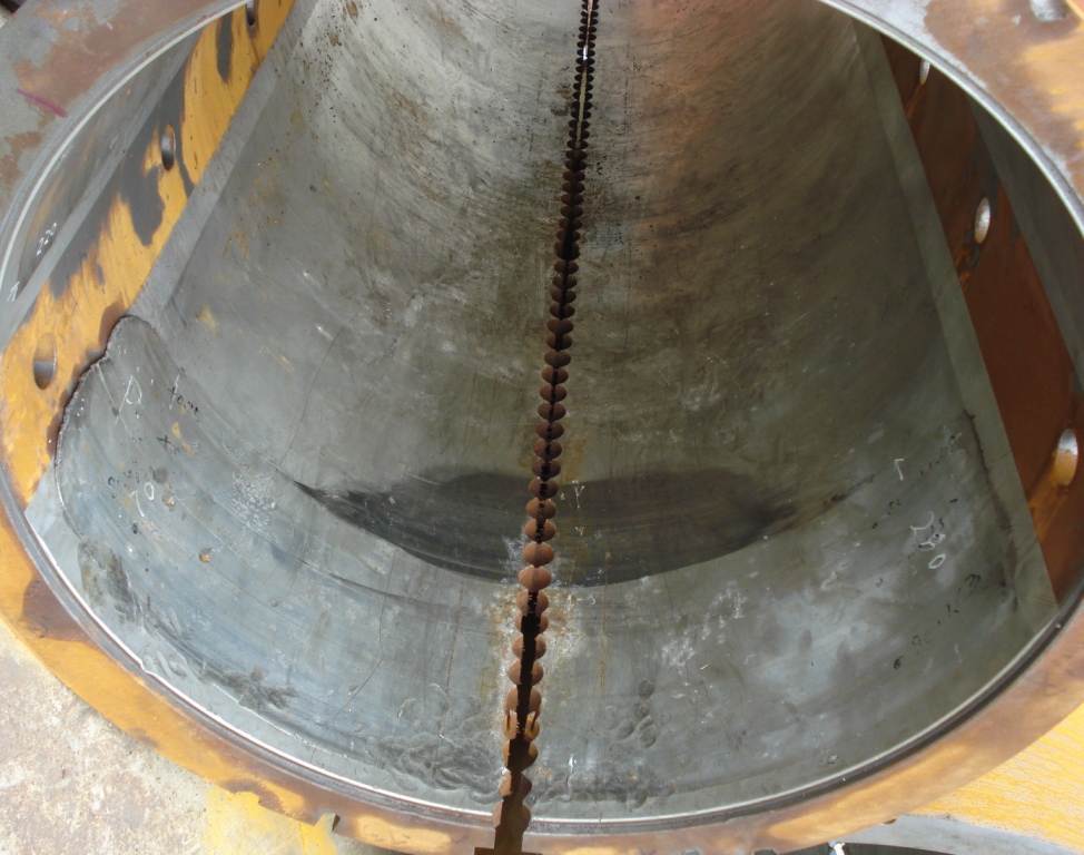
An oil lubricated sterntube aft bearing is 2x shaft diameter in length. This is for the static mass load and propulsive hydrodynamic forces acting on the propeller. A long bearing also aids in damping the vibratory element of propulsive forces due to the propeller blades acting in the unsteady wake in-flow.
Thermal wipe damage at the extreme aft end, 6 o’clock position is a common failure mode. Whitemetal bearings are not tolerant of excessive edge load. With a long bearing, the difference in reaction loads at the fwd and aft ends is sensitive to bearing slope (and relative to the shaft). Shaft bending due to mass load and propulsive forces of the propeller also affect the reaction loads at each end of the bearing.
For optimum sterntube bearing alignment Brabon Engineering Services arrange a modest load bias to the aft end of the bearing in the stopped condition during shipyard dry docking repair, i.e. the forward end is not unloaded. This provides satisfactory operation at slow, and full away, shaft speeds. At high shaft speed/ power the thrust eccentricity is typically above the propeller centre resulting in a load bias to the forward end of the bearing.
See the shaft alignment principles and shaft alignment measurements pages for more information.

1 April 2021, Machinery failure analysis and troubleshooting
Damage mechanism categories
Seemingly intractable mechanical machinery damage problems often involve multiple contributory factors.
Moreover, mechanical failures can typically involve multiple, commonly encountered, factors/ phenomena. Unusual anomalies, by their nature, are less frequently encountered. For example, bearing failure due to oil starvation is more common than say shaft lateral vibration resonance (whirling). The timing/ succession of each event can be pivotal in the (overall) failure. The challenge is to correctly discover the root cause(s) from all the available evidence.
Considering various damage mechanisms:
- Fatigue failure. This can occur irrespective of a conservative margin between yield strength and mean loading. This margin is generally indicated by the relative size of the final overload area. A fatigue fracture surface is characteristically different to that of an overload failure at microscopic and macro scale, e.g. beach, arrest and ratchet marks. The shape/ orientation of fracture face indicates the type of stress having caused propagation, e.g. a spiral fracture face would be associated with torsional fatigue. Although the dominant stresses may change as the crack propagates through the component section.
- Material deficiency or change. This may involve metallurgical imperfections such as forging lap, non-metallic inclusions, casting voids or corrosion.
- Assembly problems. This can include fasteners not tightened, looseness of fit/ seizure.
- Elastic/ plastic deformation. This is generally readily identified although the cause of overload may not be clear. It is also possible for heavy vibration to generate excessive stresses, although this occurs infrequently. In this scenario it is important to distinguish between high levels of (source) excitation forces, and resonance (response) conditions.
- Leakage/ compromised fluid containment. Seal leakage may be due to normal wear and tear or lack of maintenance. In some cases, shaft vibration can manifest with seal leakage.
- Wear and deterioration of running or mating surfaces, including fretting and corrosion.
24 March 2021, Ship propeller shaft
Non-metallic sterntube bearing failure trends
When considering non-metallic/ composite and whitemetal sterntube bearings, there are reasons for and against each option. For example, whitemetal bearings have a slightly lower failure rate, whereas non-metallic bearings tolerate bedding-in and a damaged bearing may possibly continue operation until a dock is available.
- Non-metallic bearing linings have a low/ poor heat transfer coefficient. The lube oil, or water, then has a greater role in heat dissipation. Any large vessel fitted with a non-metallic sterntube bearing can suffer a high temperature event as a result of heavy manoeuvring, e.g. emergency stop. (Note, the shaft should not be stopped in the event of damage being suspected.)
- Non-metallic bearing linings can suffer gradual cumulative damage due to loading and heat. This can lead to cracking, delamination and material loss. Poor alignment can be a factor in damage to non-metallic bearings.
- Non-metallic, water lubricated bearings can suffer damage by heavy abrasive wear due to contamination of the lube water (closed circuit system), or operation in silt laden estuaries (open systems). Vessels having open A-brackets and an operating profile involving extended idle time may be susceptible to abrasive wear due to hard marine growth on shaft journals forming during shut down periods.
It is also interesting to note that whitemetal lined bearings tend to run at slightly higher temperature where the sterntube is fixed with epoxy chock in the stern frame. This is typically due to a reduced heat transfer to the ambient water via the epoxy layer.
See the hydrodynamic bearing design and damage page for more information.

18 March 2021, Ship propeller shaft
White metal sterntube bearing failure trends
Failures of oil lubricated sterntube bearings are rare events with low occurrence rates across the global fleet. With many bearing failure incidents the causes are unknown due to incomplete investigation.
- Tankers and bulk carriers tend to be more susceptible to bearing problems, i.e. having highest failure rate. This is due to typical design having shorter shaftlines and spans between bearings, resulting in bearing loads sensitive to hull flexure and having less margin versus alignment.
- Any large vessel can experience bearing damage due to adverse/ large sterntube bearing loads during heavy manoeuvring, e.g. zig-zag or emergency stop.
- Any class of vessel may succumb to sterntube bearing damage due to stern seal failure/ deterioration and sea water contamination of the lube oil. Deferral of a scheduled seal overhaul should be carefully considered.
- Sterntube bearing problems occurring within the construction warranty period clearly suggests sub-optimum alignment. For example, bore alignment measurements in the construction shipyard using the piano-wire method without correction for sag in the wire.
In addition, cases where sterntube bearing failure has been attributed to the use of EAL lube oil are more likely, in reality, to be the result of poor alignment possibly compounded with other contributory factors. Shipyards have been known to blame the EAL oil as a convenient contrivance to evade a warranty claim.
Non-metallic sterntube bearings, tend to have a higher overall failure rate than whitemetal lined bearings. However, trends are difficult to identify with little variation between individual vessels and vessel types.
See the hydrodynamic bearing design and damage page for more information.

10 March 2021, Ship shaft alignment measurements of bearing loads by jacking or strain gauges?
The methods used by the alignment engineer are only one aspect of undertaking an alignment assessment during a dry docking repair. It is important that shaft alignment measurements of bearing loads are conducted with the ship afloat and at an operational draught aft. If there are no measurements with the vessel afloat, then any alignment adjustments are less certain.
Strain gauges can be affixed to the shaft in the accessible spans. Shaft bending inboard near the sterntube is related to load distribution on the sterntube aft bearing (vertical and horizontal). Very few shipyards are capable of this measurement technique. Bending strain measurements offer a means of establishing if there is satisfactory alignment in the sterntube aft bearing.
Bearing loads can also be derived by shaft jacking measurements. However, the jack needs to be located immediately adjacent to the bearing, i.e. accessible. A jacking measurement where the load and lift are manually recorded from jack pressure and a dial indicator, as favoured by many shipyards, may only give a handful of data points with the indicated load being affected by friction in the jack. Loads measured using a strain gauge load cell and data logger provide more accurate results. Application of the correct jack correction factor also helps with the load results.
See the shaft alignment principles and shaft alignment measurements pages for further information.

4 March 2021, Ship sterntube bearing bore alignment measurements using optical or laser equipment?
The tools used by the alignment engineer are only one aspect of the tasks within a typical dry docking attendance to assist with a ship propulsion shaft alignment problem. Other equally important tasks include assessment of all measurement results/ observations as well as deriving recommended offsets/ adjustment for (any) replacement sterntube bearing. It is important that the calculations of bearing (offset) adjustments follows a rigorous procedure with identification of all uncertainties.
Brabon Engineering Services opt to use the Taylor-Hobson micro-alignment telescope and target jigs. Experience shows this is superior as a complete measurement system to laser alignment. Bearing/ housing offsets relative to the datum/ reference line of sight are measured with the vertical/ horizontal direction micrometers of the alignment telescope. Post-processing image analysis/ scaling also assures an accuracy of better than 0.01mm.

25 February 2021, Ship propulsion shaft alignment procedure
If sterntube bearing damage is suspected, then a co-ordinated process is needed to ensure a satisfactory repair and return the vessel to service/ charter. For a sterntube bearing operating with little margin, then reinstating the original design bearing offsets/ slope would likely incur significant risk of further damage.
Important steps in the process:
- Accurate measurement of shaftline bearing loads in the afloat condition prior to vessel docking. Poor jacking measurements can fail to identify adverse bearing loads. Strain gauge shaft bending measurements are also generally recommended as this provides additional information of bearing loads.
- Optical/ laser measurement of (existing, damaged) sterntube bearing bore slope as well as bearing housing slope (after bearing extraction). An accurate, rather than rapid, measurement should be the primary objective for this step. Use of appropriate reference datums for both measurements is needed to provided data that can be compared to design.
- Assessment of measurement results along with the observed condition on the sterntube bearing in order to prepare any recommended alignment adjustments. While this step always involves judgement, it should be based on a proven methodology.


This site stores cookies on your device. These cookies are used to collect information about you interaction with our website and allow us to remember you. We use this information to improve and customize your browsing experience as well as for metrics and analysis about our website visitors.